Introduction
Welcome to another edition of anynode training videos. In this episode of our anynode video tutorials, which is aimed at advanced anynode users, we invite you to sit back and watch as we share with you information on using SIP URI processing to read and assemble the information from a SIP message.
To better understand the processes involved in SIP URI processing, let’s take a look at how anynode works as a SIP-to-SIP user agent.
How a SIP-To-SIP User Agent works
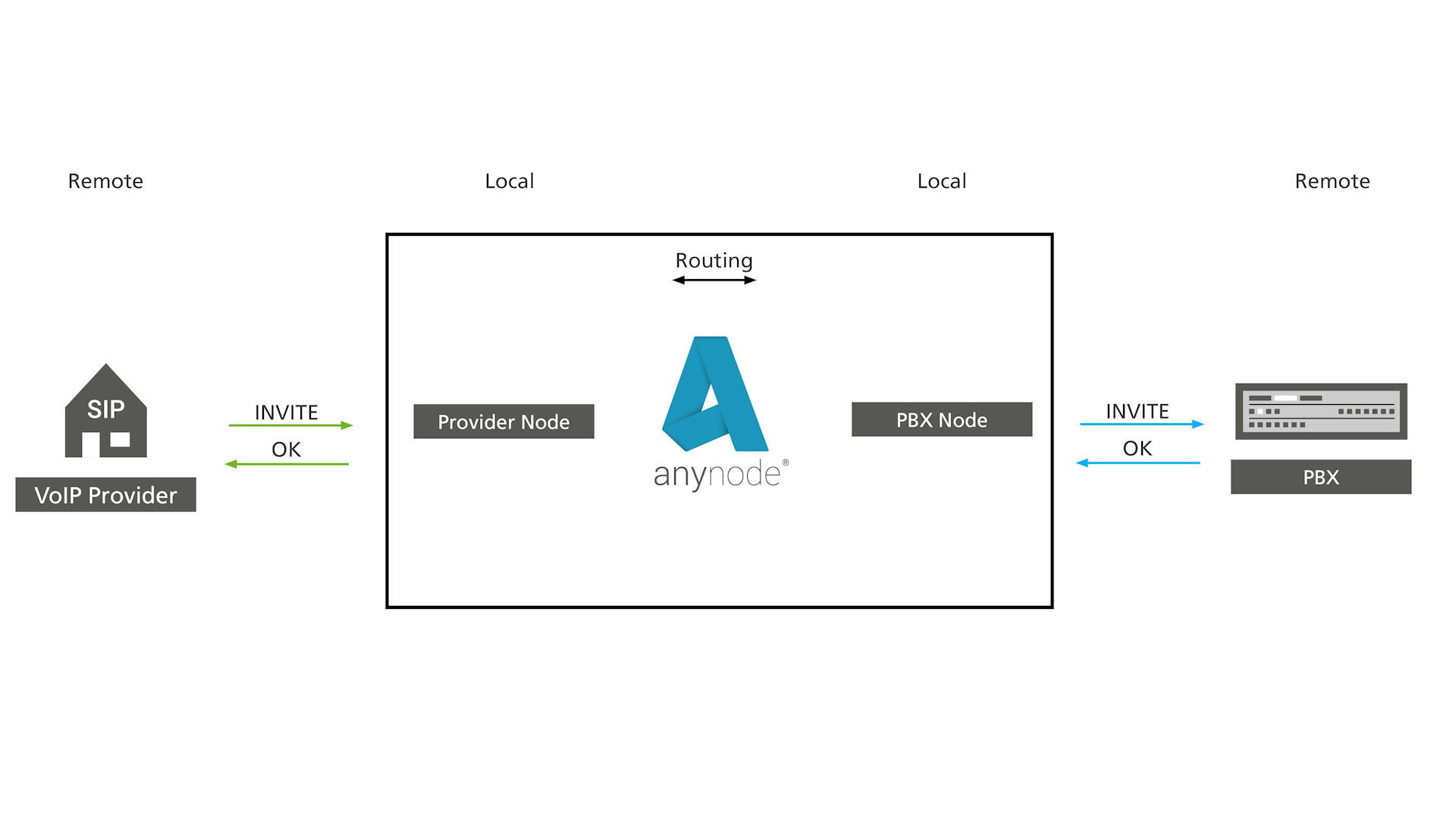
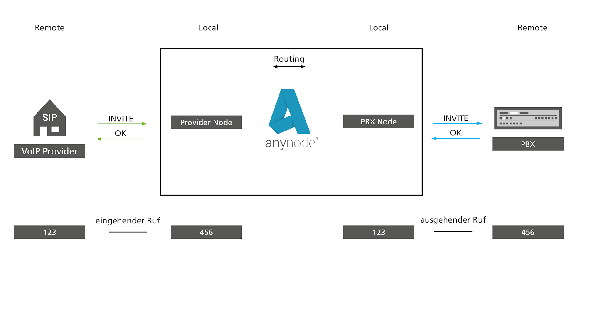
Here, two endpoints do not communicate directly with each other, but anynode terminates the SIP messages of the source node and creates for the target node new messages which are independent of the source node SIP messages. Thus source and destination endpoint know nothing about each other, both know only anynode as a remote site. This ensures that no SIP messages unknown to the destination endpoint are delivered. In addition, if anynode acts as a session border controller between an external and an internal network, the internal SIP communication and the infrastructure remain invisible.
pbx.anynode.com
Routing Domain
A separate node must be created in the anynode configuration for each remote site. In addition to the transport, SIP, and media parameters, the node settings also offer options for adapting telephone numbers.
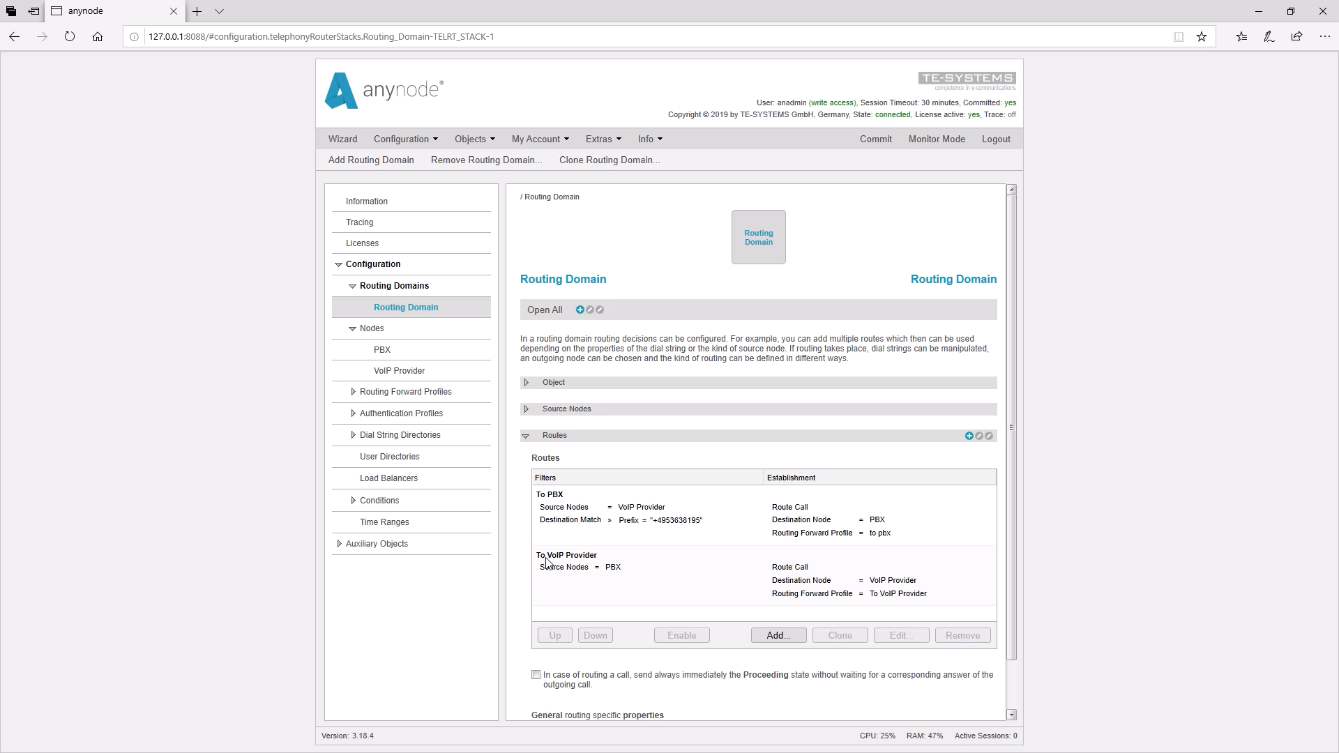
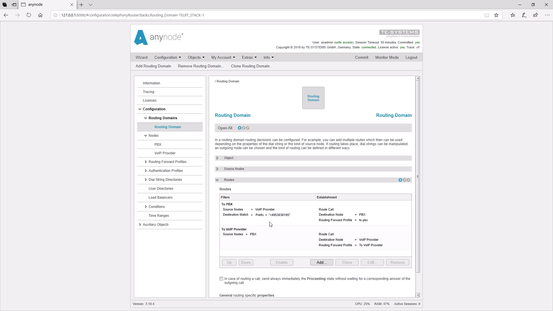
The connection between the individual nodes is established via route tables, the so-called routing domain.
A call always goes through an incoming node and an outgoing node. These nodes are always connected via routing. So you receive 2 separate calls.
Routing decisions are mostly made using dial strings. The dial strings result from the associated URIs, i.e. Uniform Resource Identifier. anynode always becomes the local site for the remote station.
In our anynode configuration, we have already created two nodes, a PBX and a VoIP provider.
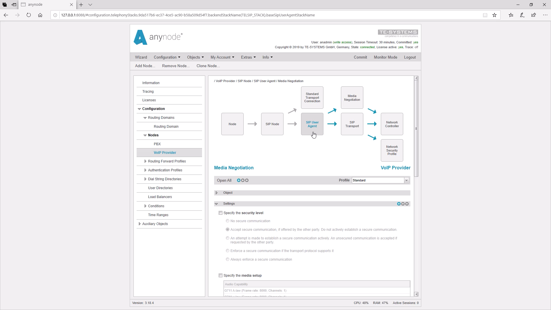
The call comes in via the network card. Next, the call goes through the SIP transport. Here special transport protocols can be set, such as UDP, TCP, and TLS. In Media Negotiation settings can be made for the treatment of the media, e.g. codecs or whether the media should be transmitted encrypted or not.
The SIP-specific settings are made in the SIP User Agent.
In the SIP Node, among other things, a number manipulation can be made, at this point, we would like to point out that there is a learning video on this topic “Basics call number manipulation and routing”.
Then the call goes into the routing where subsequently an outgoing call is initiated. In the outgoing node, the call now goes through the other order.
SIP URI Processing in SIP User Agent
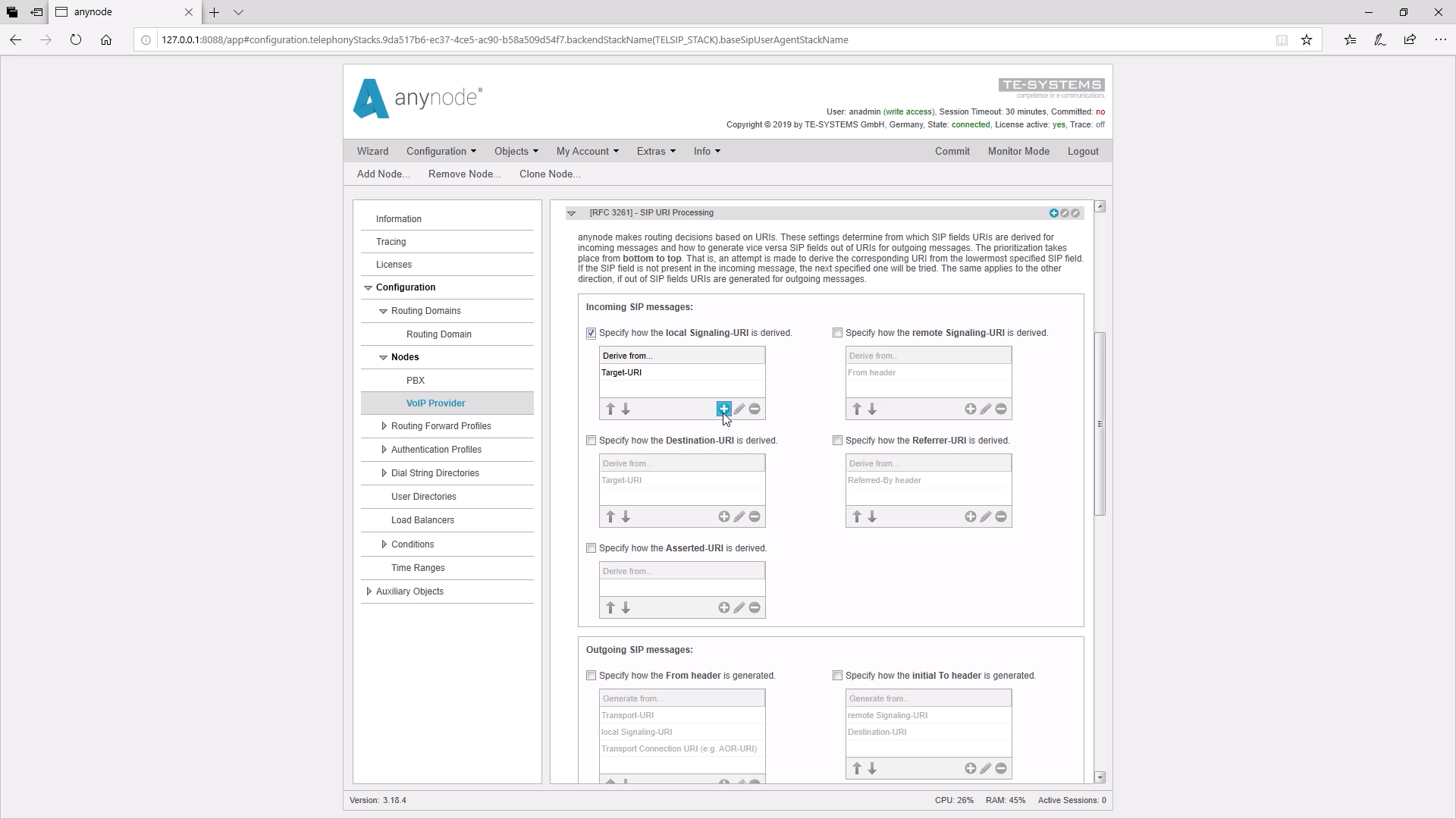
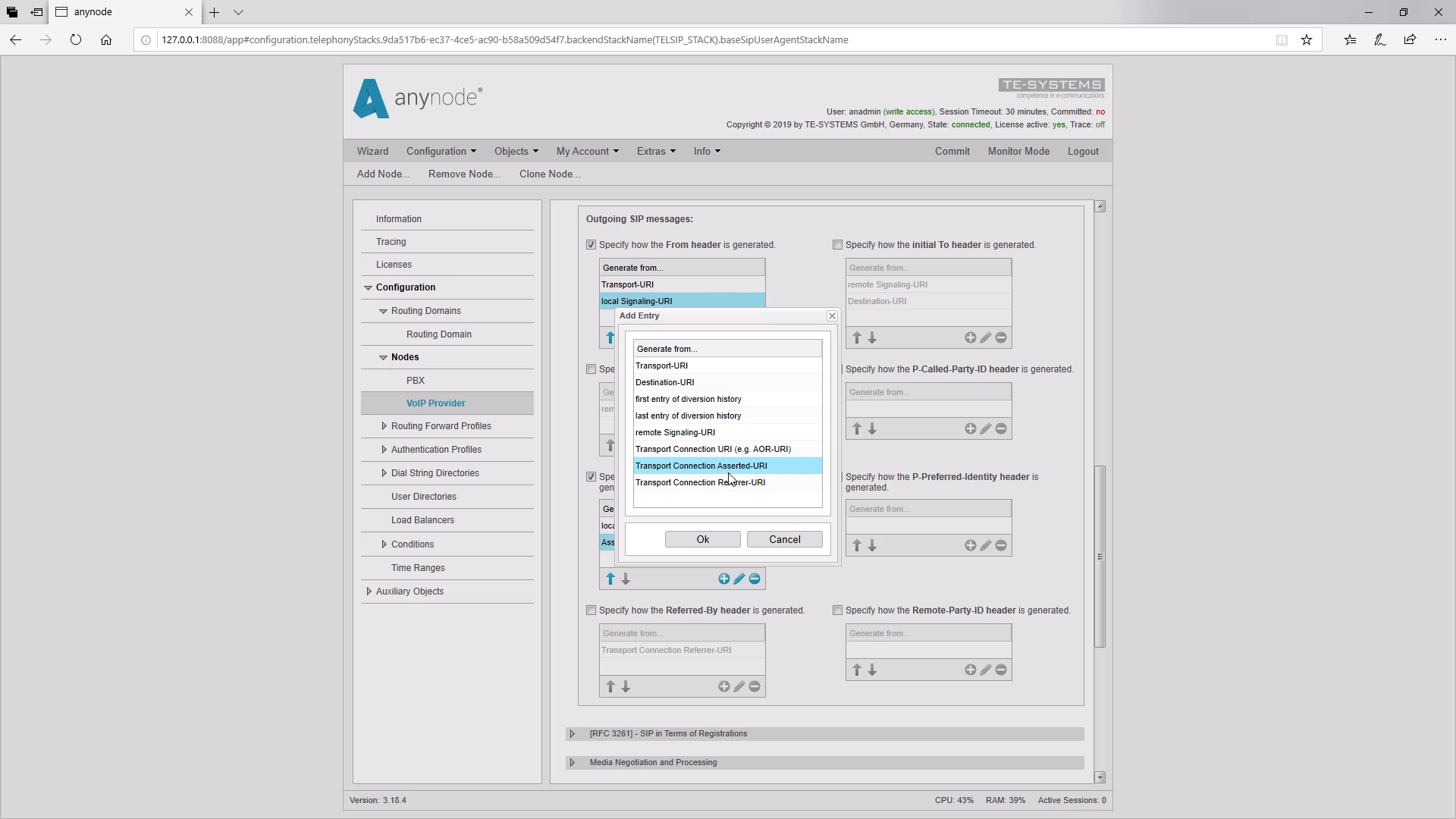
Now let’s take a closer look at SIP URI Processing. As mentioned earlier, most of the route decisions are made using dial strings. The dial strings result from the associated URIs. At this point, we can determine from which SIP headers an incoming SIP message URIs should be obtained. By setting the tick, we can deviate from the standard values if necessary and add further inputs with the plus sign.
For outgoing calls, it can be defined where the SIP message should take the values for the individual headers.
Here the local signaling URI is defined. This is the called address of the anynode system.
The destination URI is the destination address to be called. This is usually a telephone number and the Local Signaling URI is the destination URI. Therefore, the default setting for anynode for both cases is the Target URI, i.e. the first line of the SIP message.
The remote signaling URI normally represents the number that establishes the call, i.e. the sender number.
The Asserted URI is a placeholder that can be used flexibly. The placeholder Referrer URI is used only in rare cases, so we will not go into more detail here.
These values can now be used for routing. When the call leaves the routing, the contents of the following fields on the outgoing SIP messages can be determined. The field for the FROM Header and for the target URI is important, as well as the field for the TO Header. The P-Asserted Identity and P-Preferred Identity fields can be used if required by the provider.
Please note that in the URI values of the input fields, the URIs will be switched after the routing, when the second call is established.
That means, after the routing, the remote signaling URI becomes the local signaling URI in the outgoing call. The local signaling URI becomes the Remote Signaling URI.
The Remote Signaling URI becomes the Source Address in the SIP node.
The Source Address contains, among other things, the Source Dial String and the Source Display name. The source dial string can then be used for routing.
The destination URI becomes the destination address. The destination address includes, among other things, the destination dial string and the destination display name.
Handling of tables
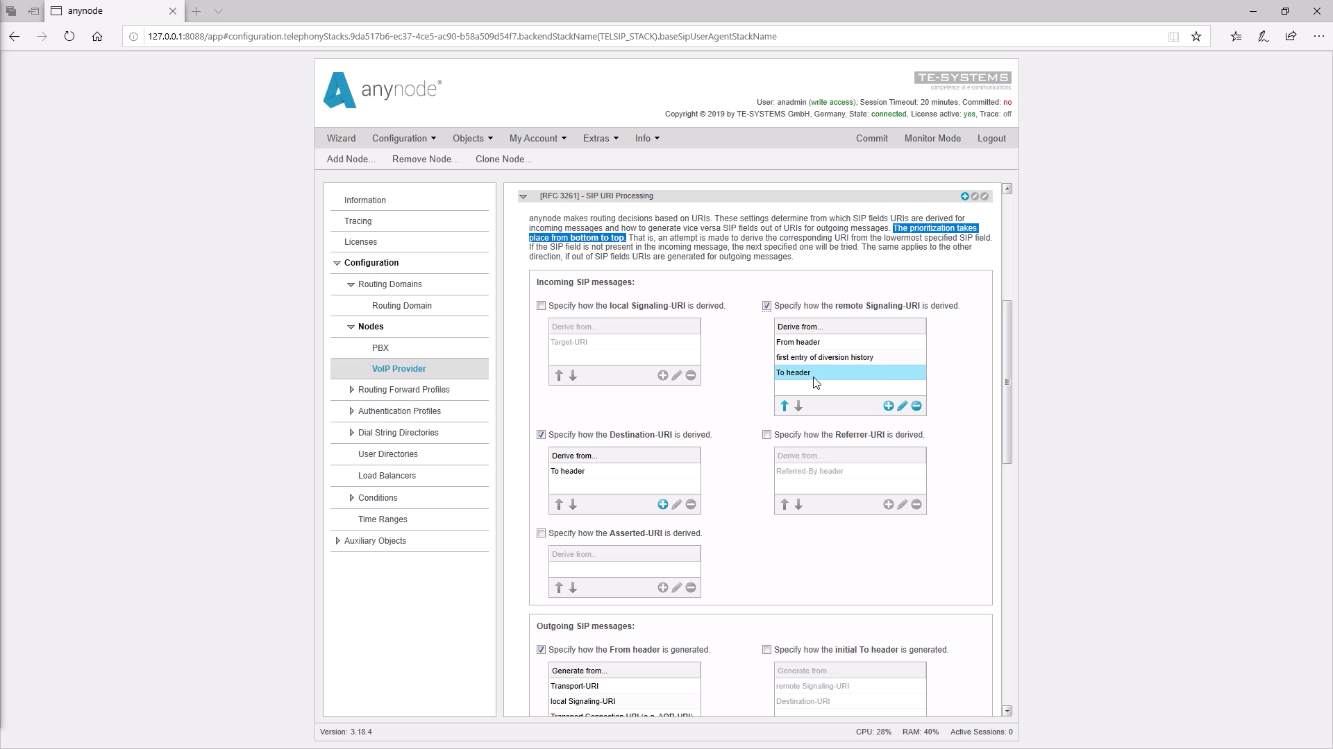
The entries in the tables are processed from bottom to top.
If there is the header in the table, then it is taken. If not, the next higher entry is taken. If there is none of these headers, the optional fields will not include the SIP header in the SIP message.
Practical example: Username in TO-Header
Now we would like to set the SIP URI processing correctly based on a practical example. n our anynode configuration, we have already created two nodes, a PBX and a VoIP provider. Of course, this PBX can be local or in the cloud. In our example, both sides can support E.164 numbers. .
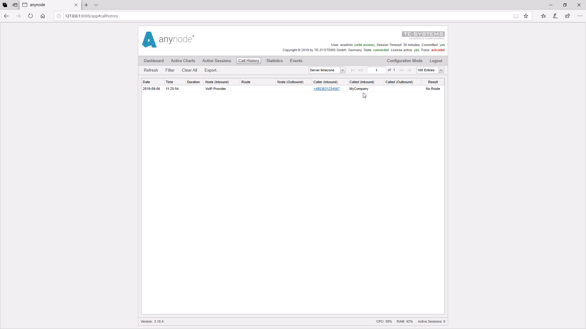
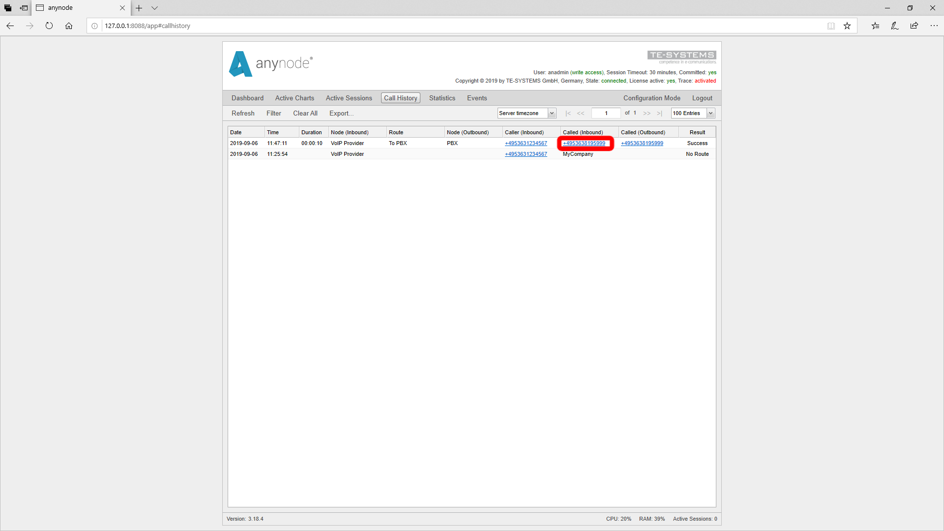
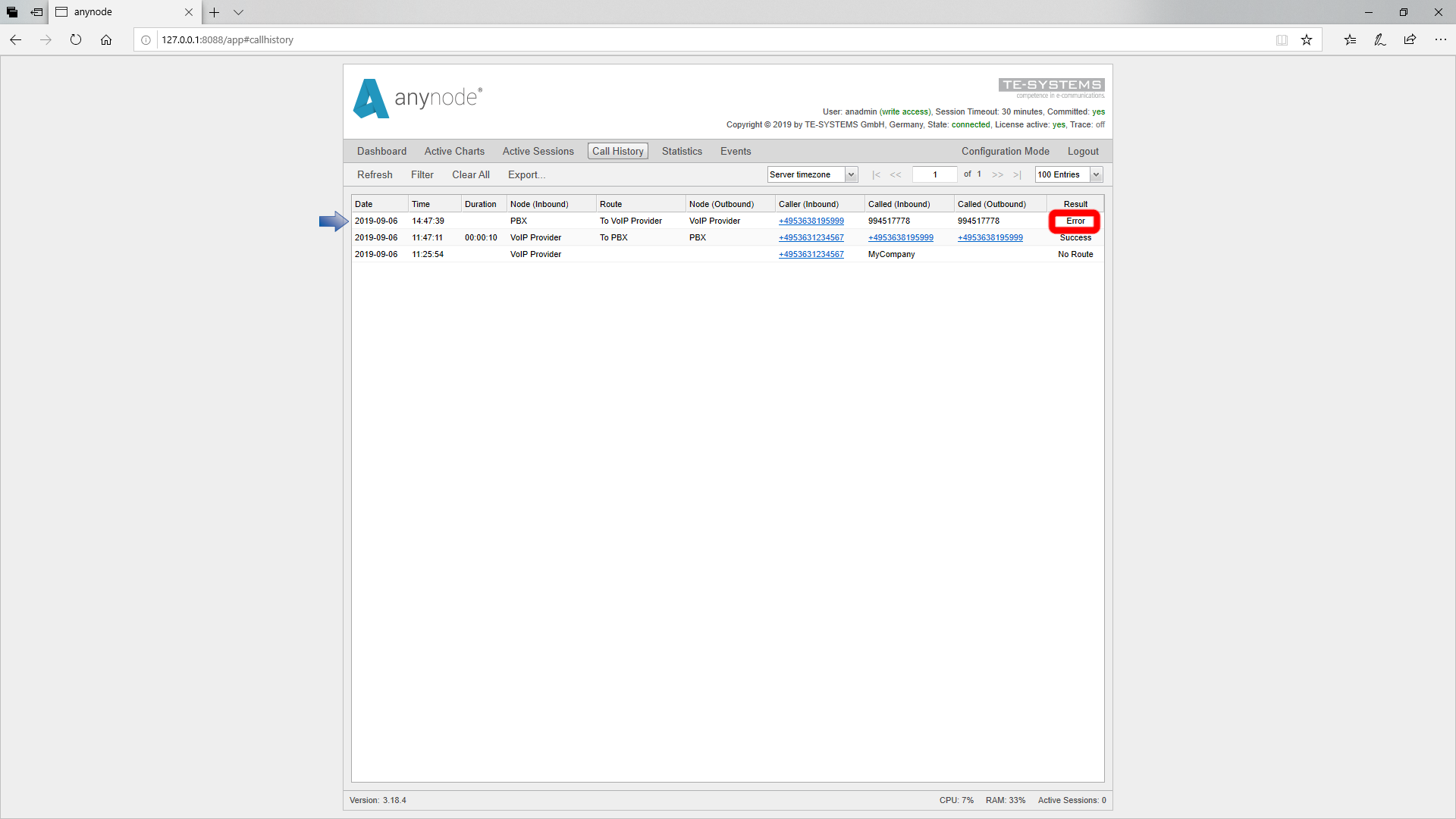
An incoming call from the provider should be routed to the telephone system. Let’s take a look into the monitor mode and see that the call comes in, but cannot be routed, because in the Called Number field a username can be seen.
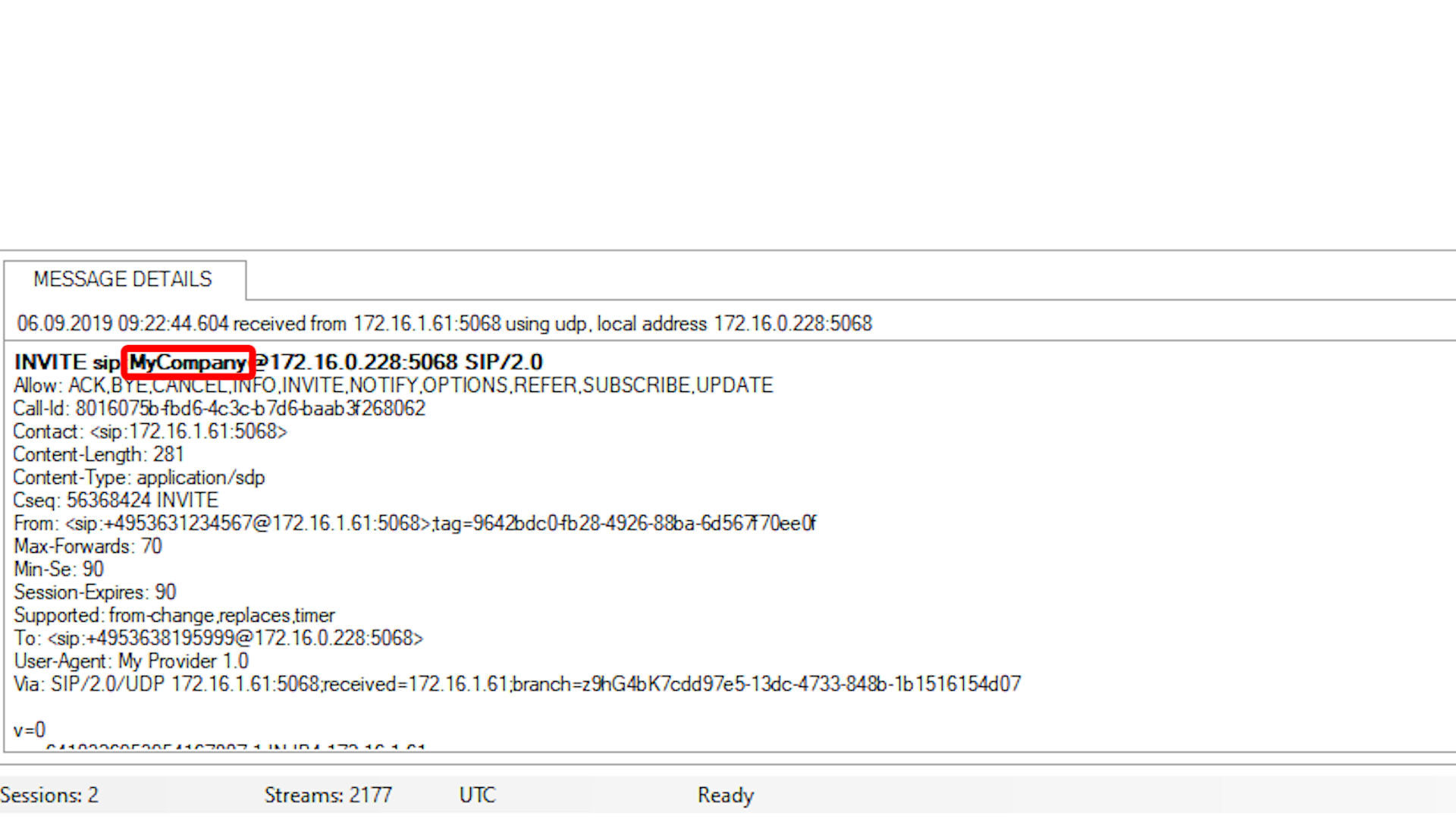
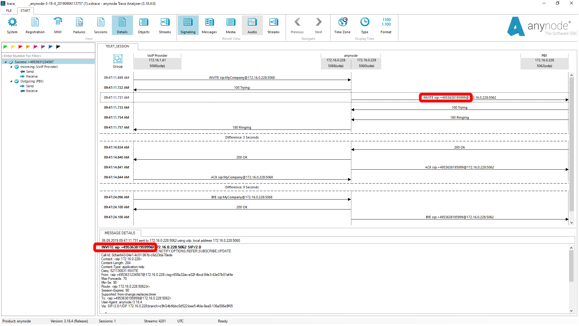
Actually, we would expect a phone number here. In the trace, we get more detailed analysis options. We have already activated a trace before.
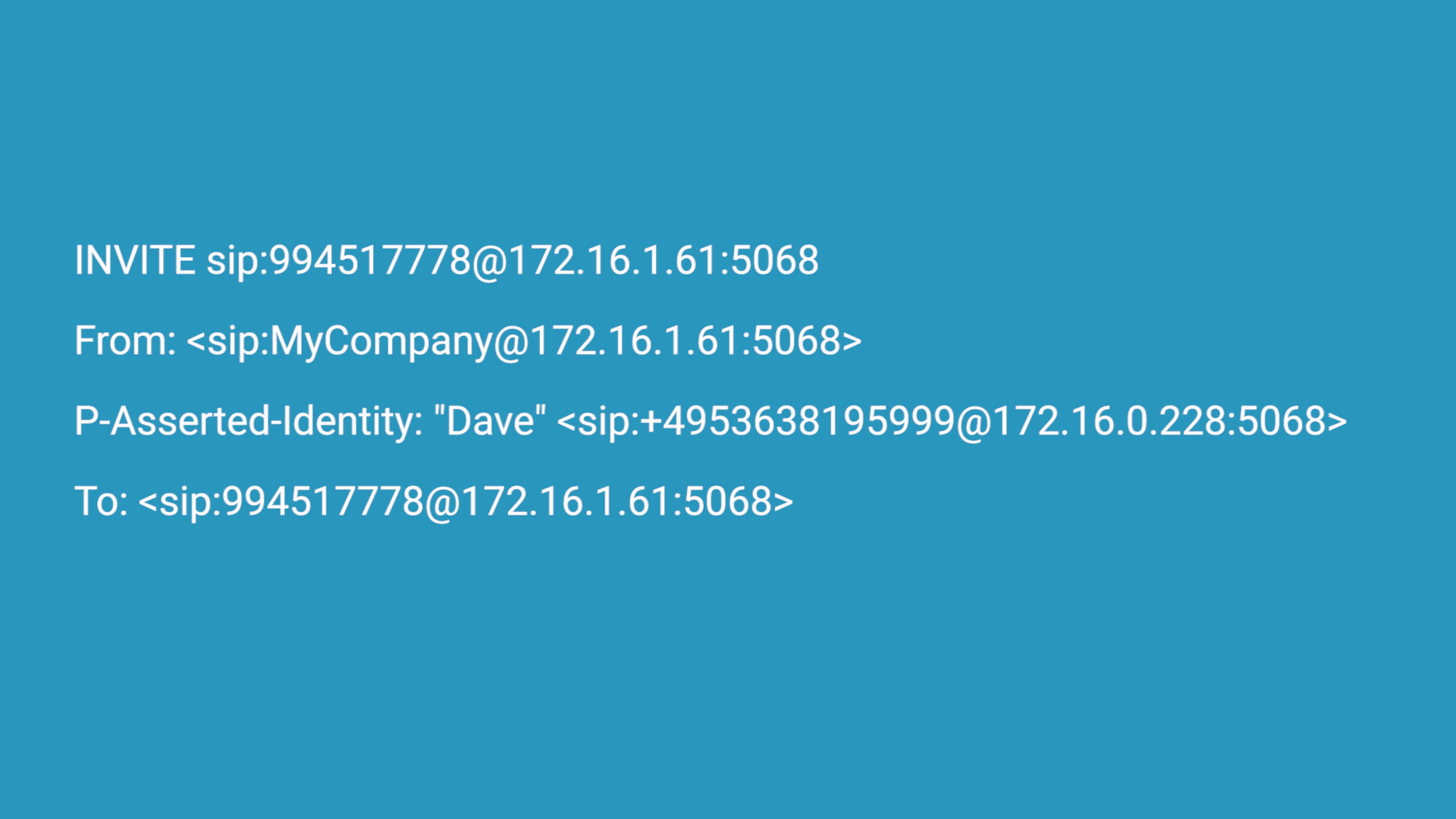
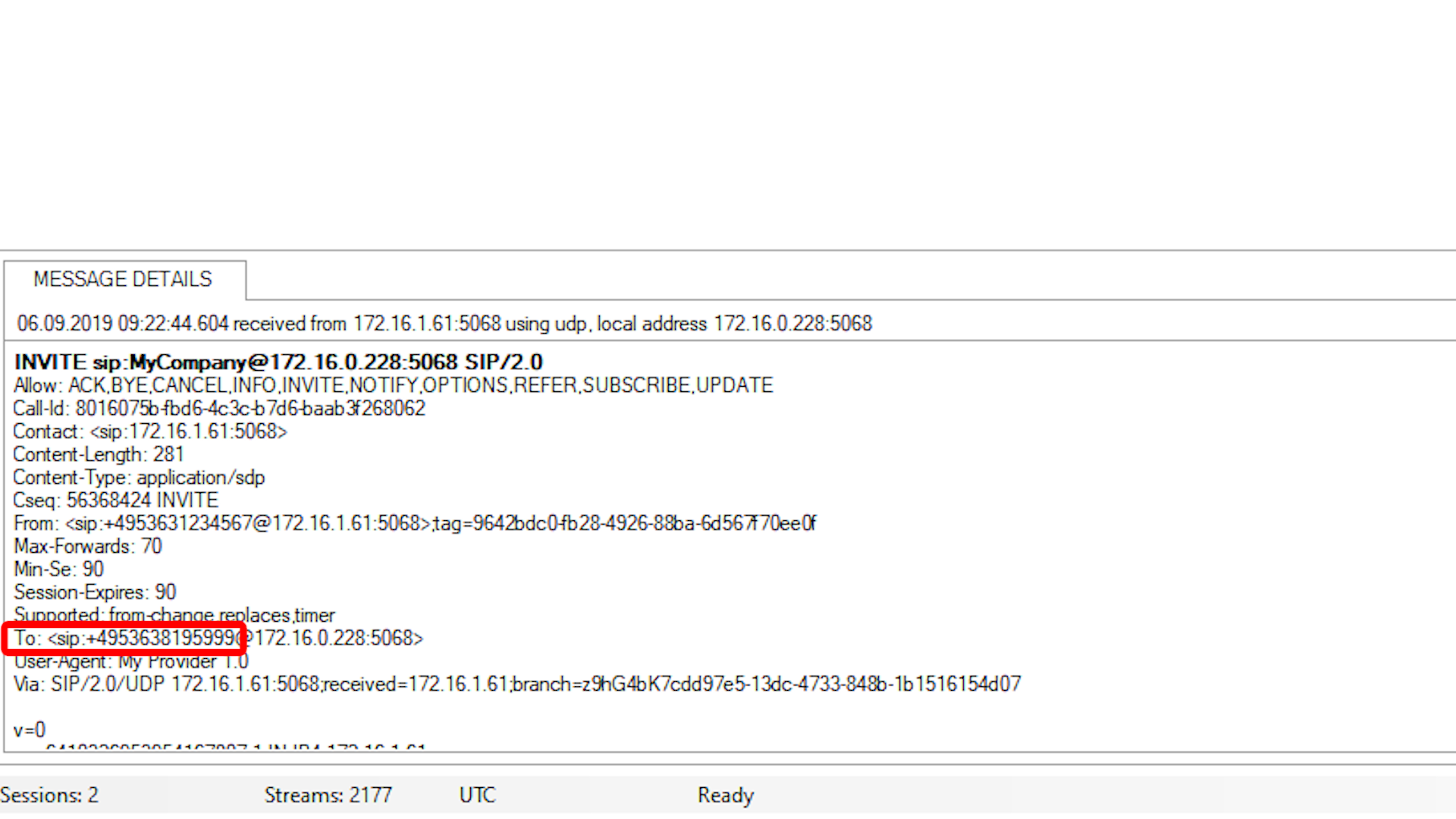
We can see here that the username is in the top line, i.e. in the target URI. We discover the phone number that has been called in the TO Field.
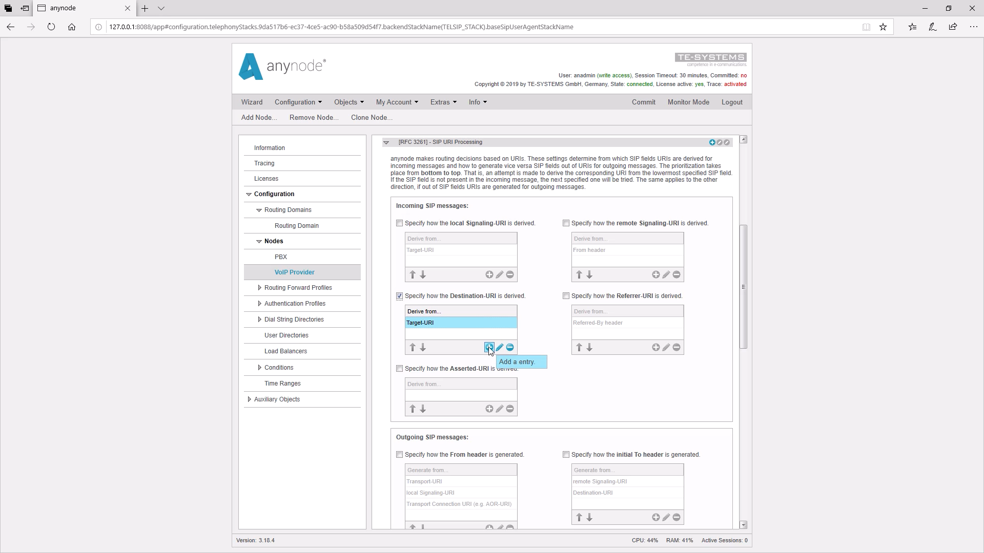
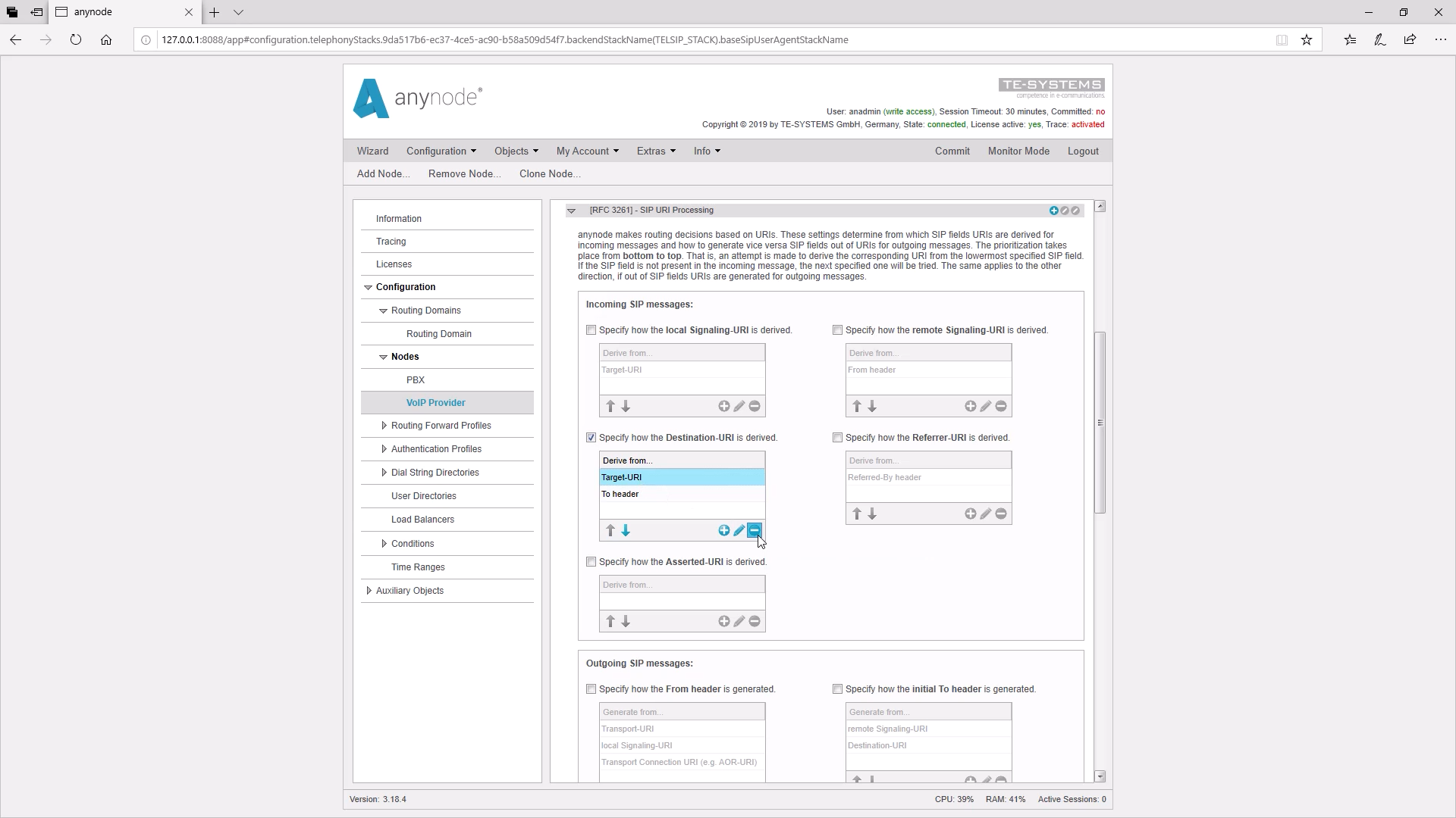
So we go back into the anynode configuration in the provider node and find there the input field for the derivation of the destination URI. As we mentioned earlier, the destination URI is taken out of the target header by default.
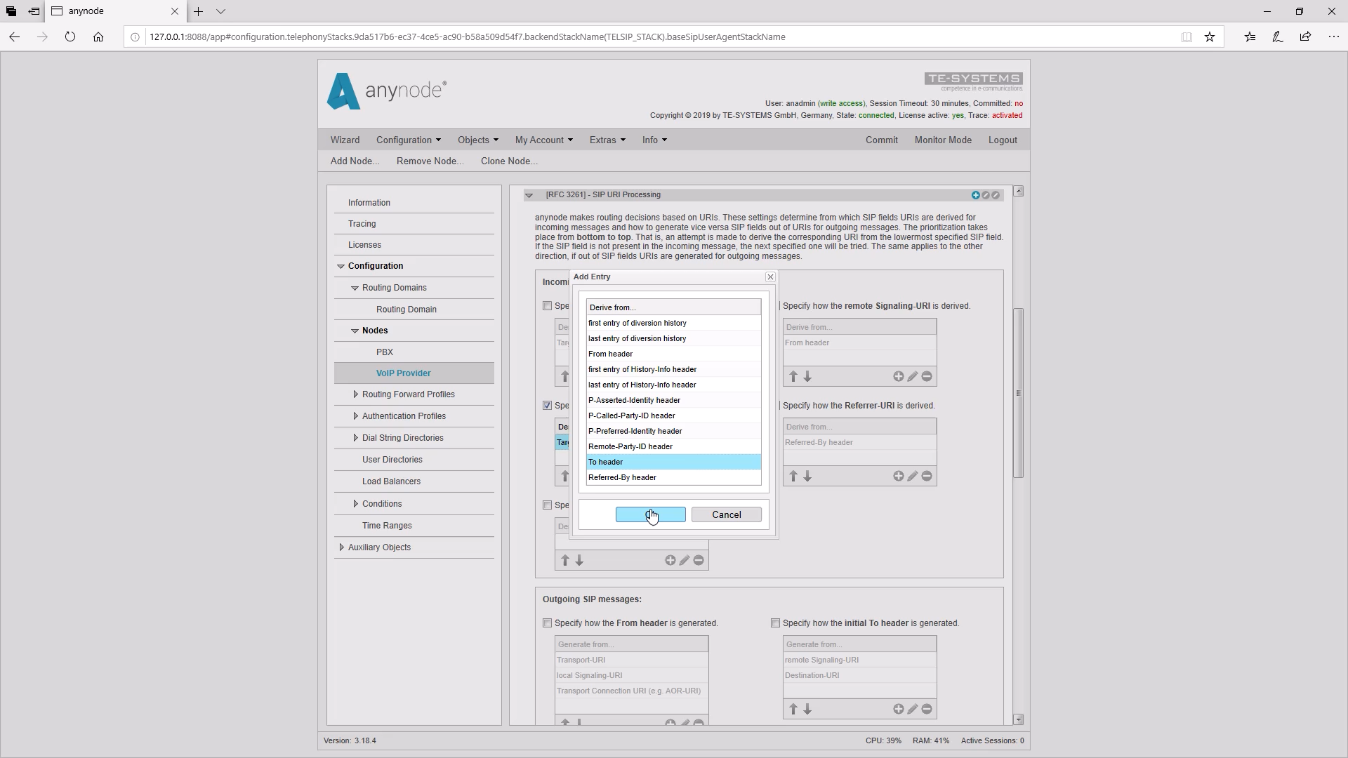
Therefore, we add the To header with the plus (+) and delete the Target URI out with the minus (-).
Afterward, we must not forget to confirm the entries with a “Commit”. Now the dialed destination number can be used correctly for the routing.
Practical example: no phone number in P-Asserted-Identity header for provider identification
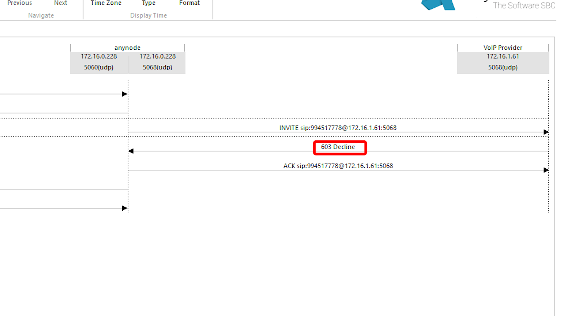
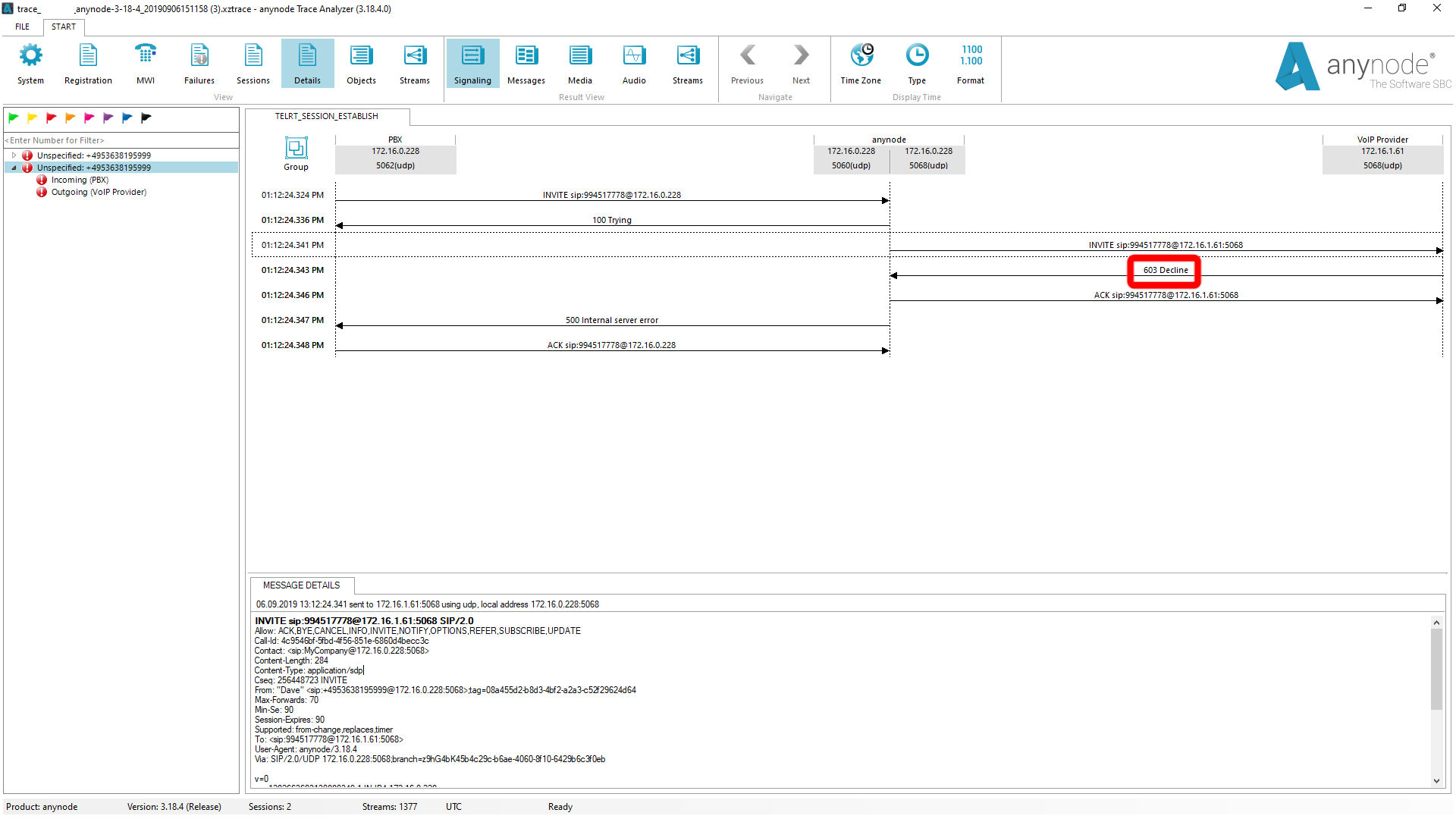
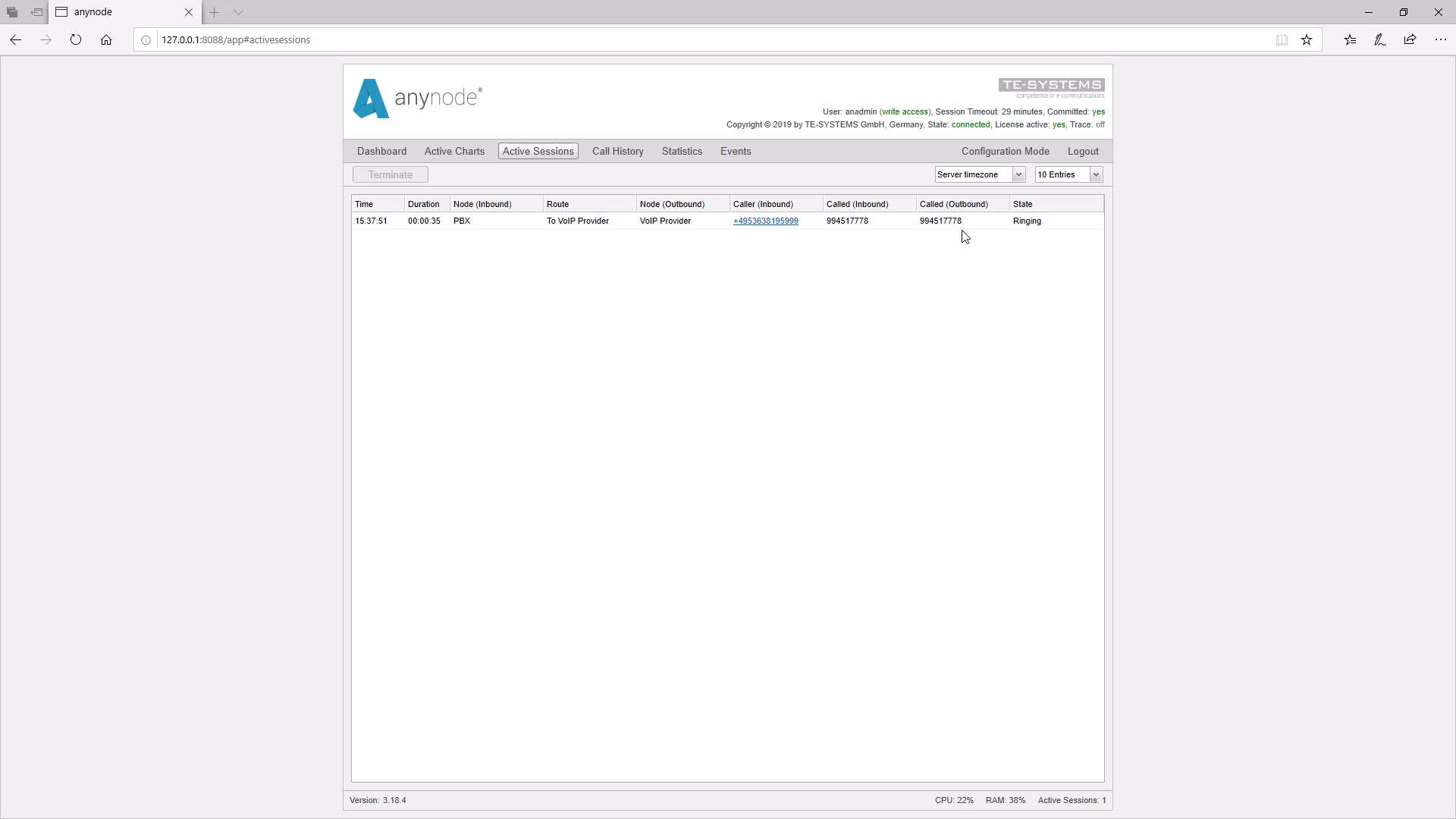
Now we make a call in the other direction to the provider. In monitor mode, we see that the call in this direction also fails. We have already run a trace and see that the provider rejects the call with “Decline”.
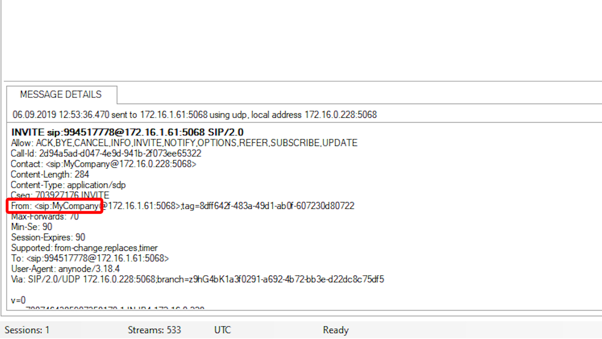
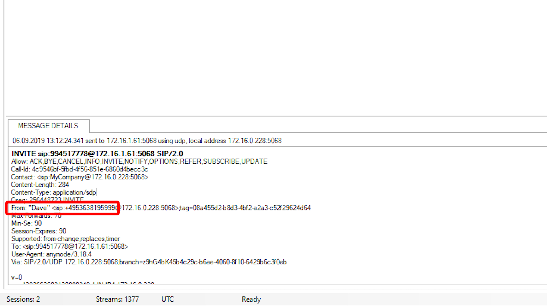
In the FROM Header, we discover that our login name, AOR, is being sent to the provider.
However, we want the recipient to receive our correct sender ID.
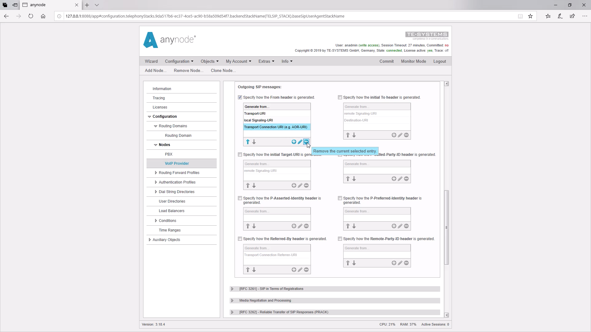
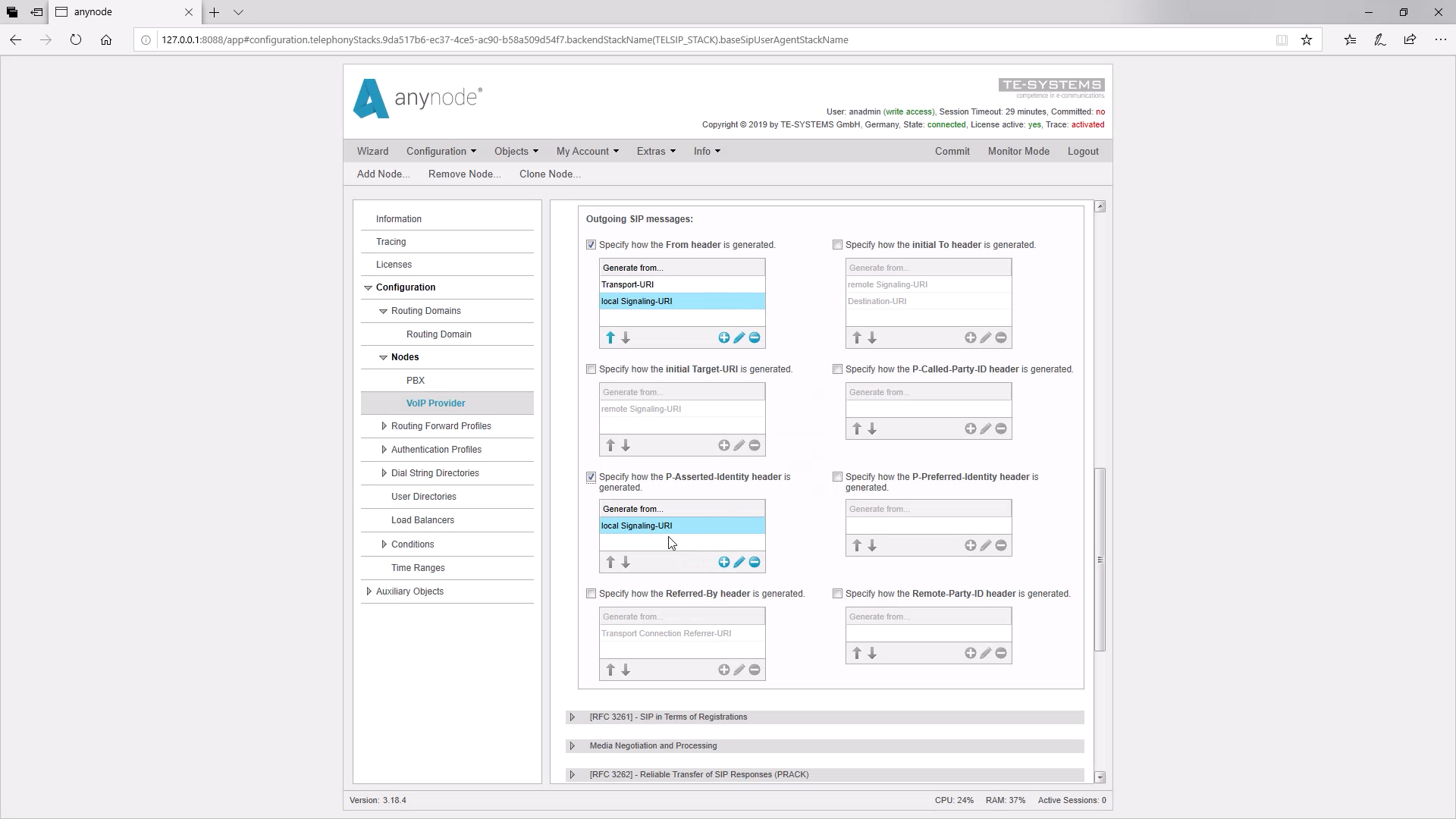
Now let’s take a look at how the FROM Header is currently being set up in our configuration.
We see that the FROM Header is taken from the Transport Connection URI, in our case the AOR. This is SIP technically correct, but in our case not effective. So we delete the line and then the Local-Signaling-URI is taken, which contains the correct sender ID.
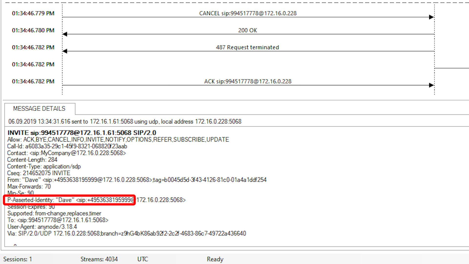
Now we test it again and see in the trace that the line with the FROM Header with the correct sender ID is transmitted.
But nevertheless, the call is declined by the provider.
Our provider has informed us about this in his contract documents: He demands our master number in the P-Asserted Identity field as identification.
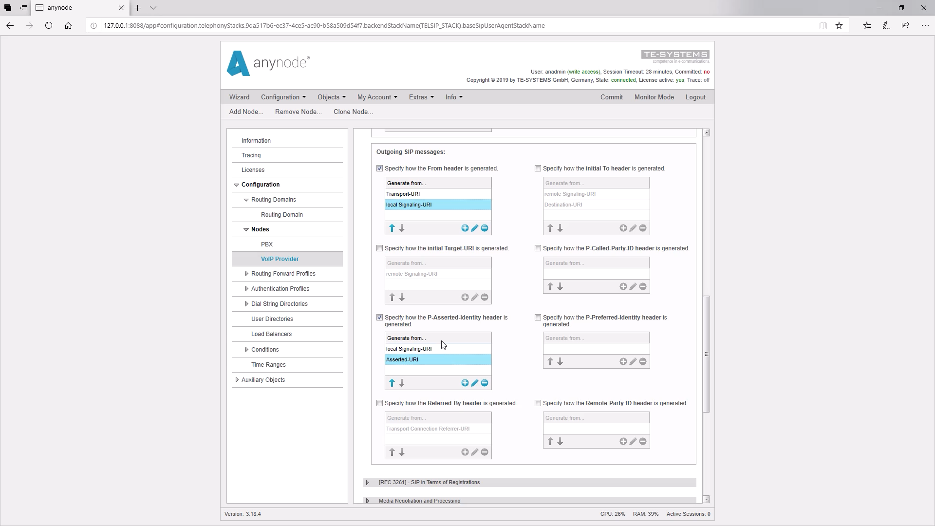
So we have to set the field P-Asserted Identity. We now determine that our number will be taken from the Local Signaling URI so that our sender number will be transmitted to the provider in the P-Asserted Identity field.
By clicking on Commit we finally confirm our submissions.
Now the call is accepted by the provider.
In the trace, the P-Asserted Identity is specified correctly.
At this point, we would like to point out a special case in the configuration which often happens in practice: The local signaling URI does not always have a value that the provider accepts.
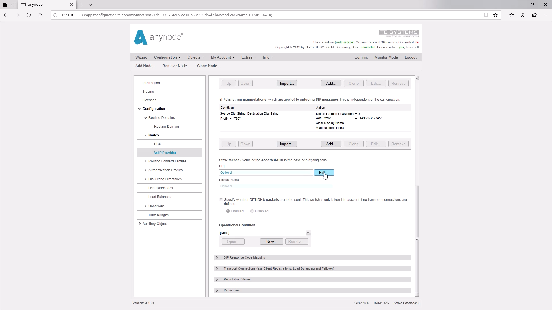
This happens at times if you want to use any foreign phone numbers or the phone number is not transmitted at phone number suppression. In such a case you have to transmit a preset phone number in the P-Asserted-Identity Header. In SIP URI processing we add the Asserted URI and this URI can be determined in the SIP node at this point.
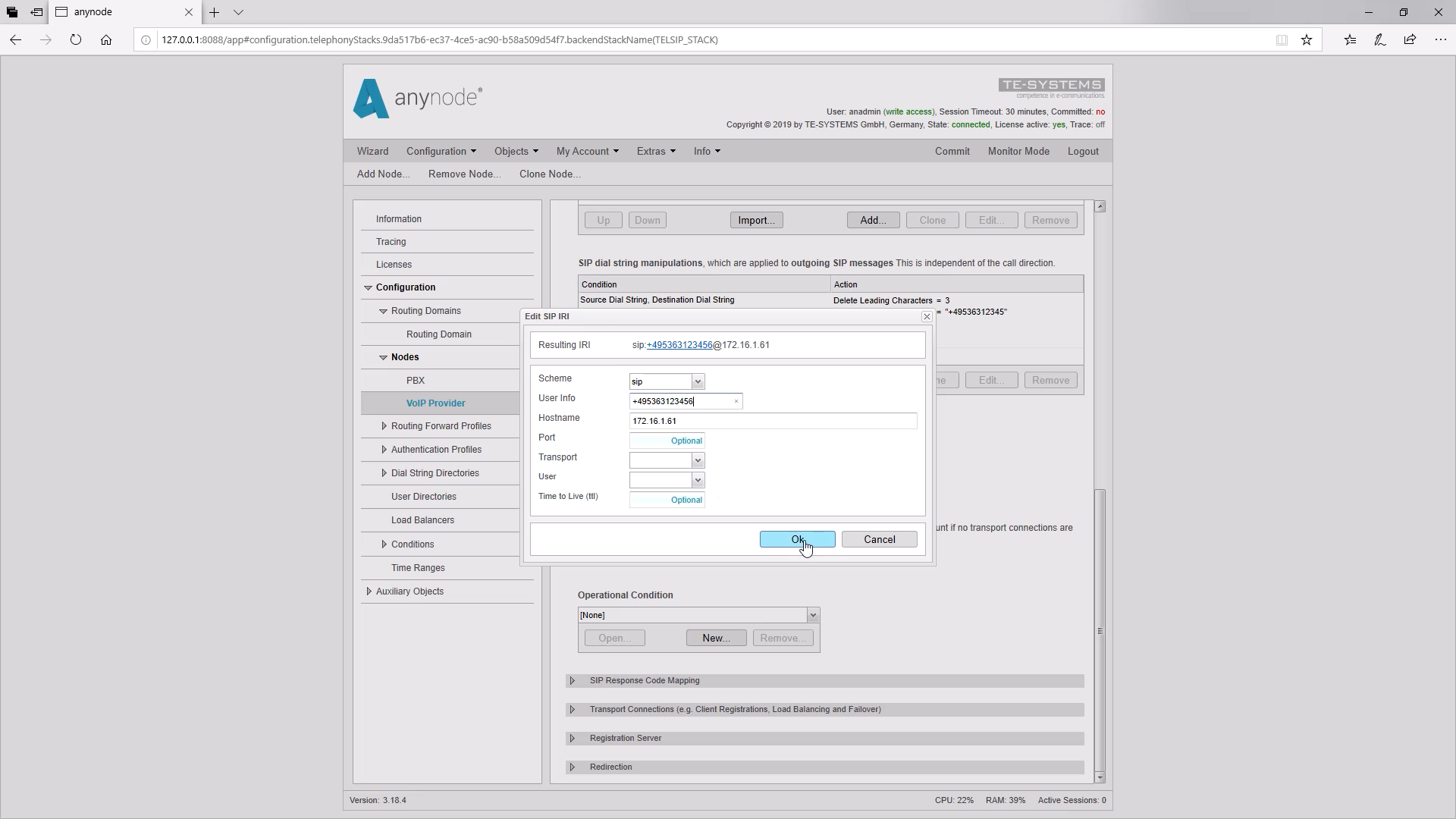
By clicking on “Edit” we can enter our root number under “User Info” and get our asserted URI.
Alternatively, if a Transport Connection is used, this can also be set in the Transport Connection Asserted URI.
So we go under Standard Transport Connection in the input field for the Asserted URI. Again, you can enter the number under User Info. The advantage of entering in the Standard Transport Connection is that the correct root number is always taken and transmitted when multiple Transport Connections are set up.
We arrived at the end of this training and thank you for your attention.


