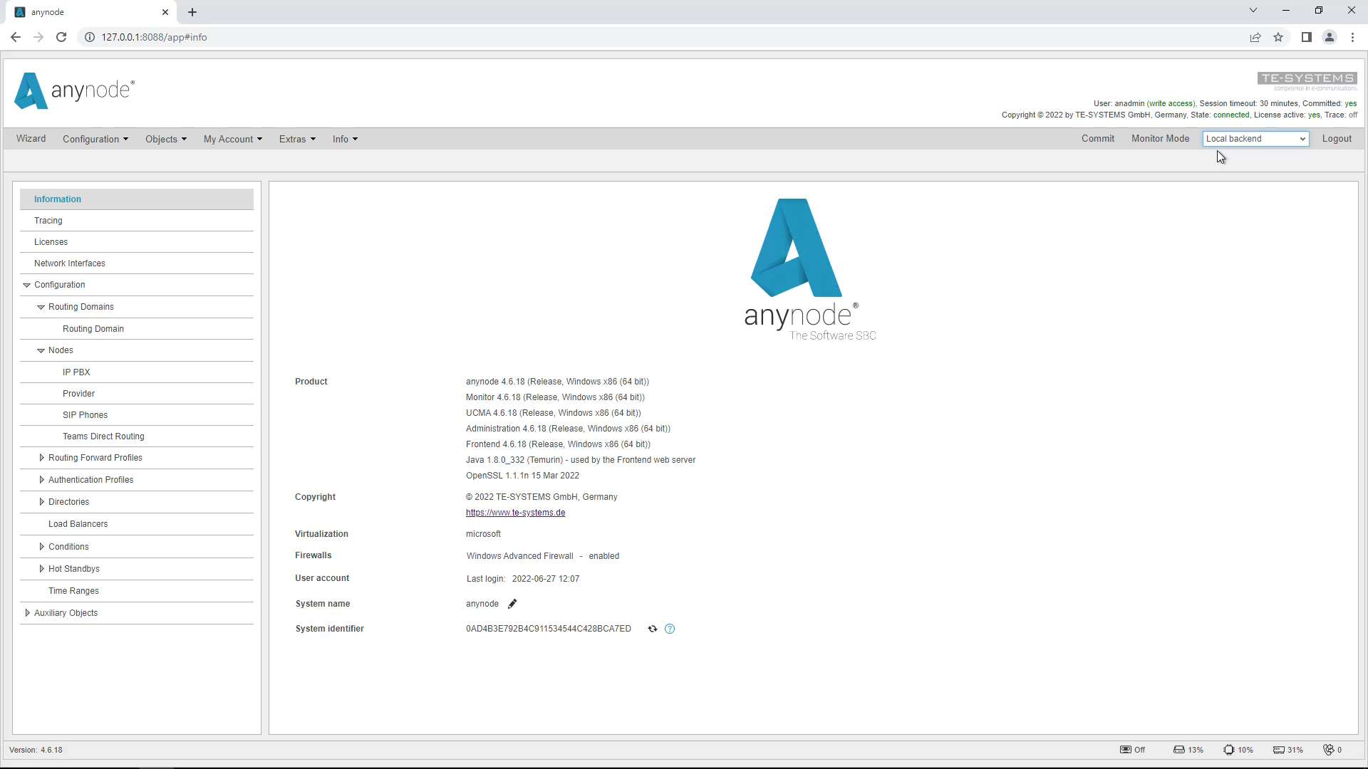
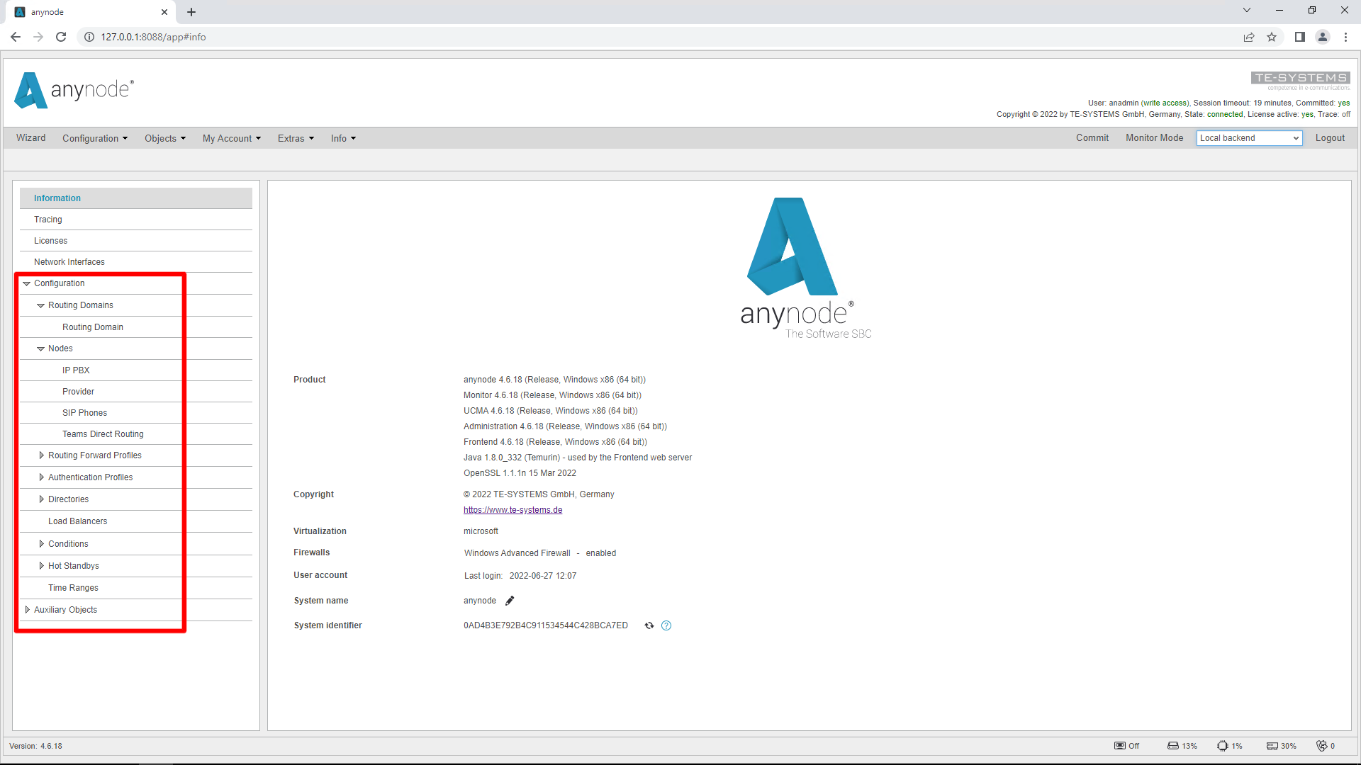
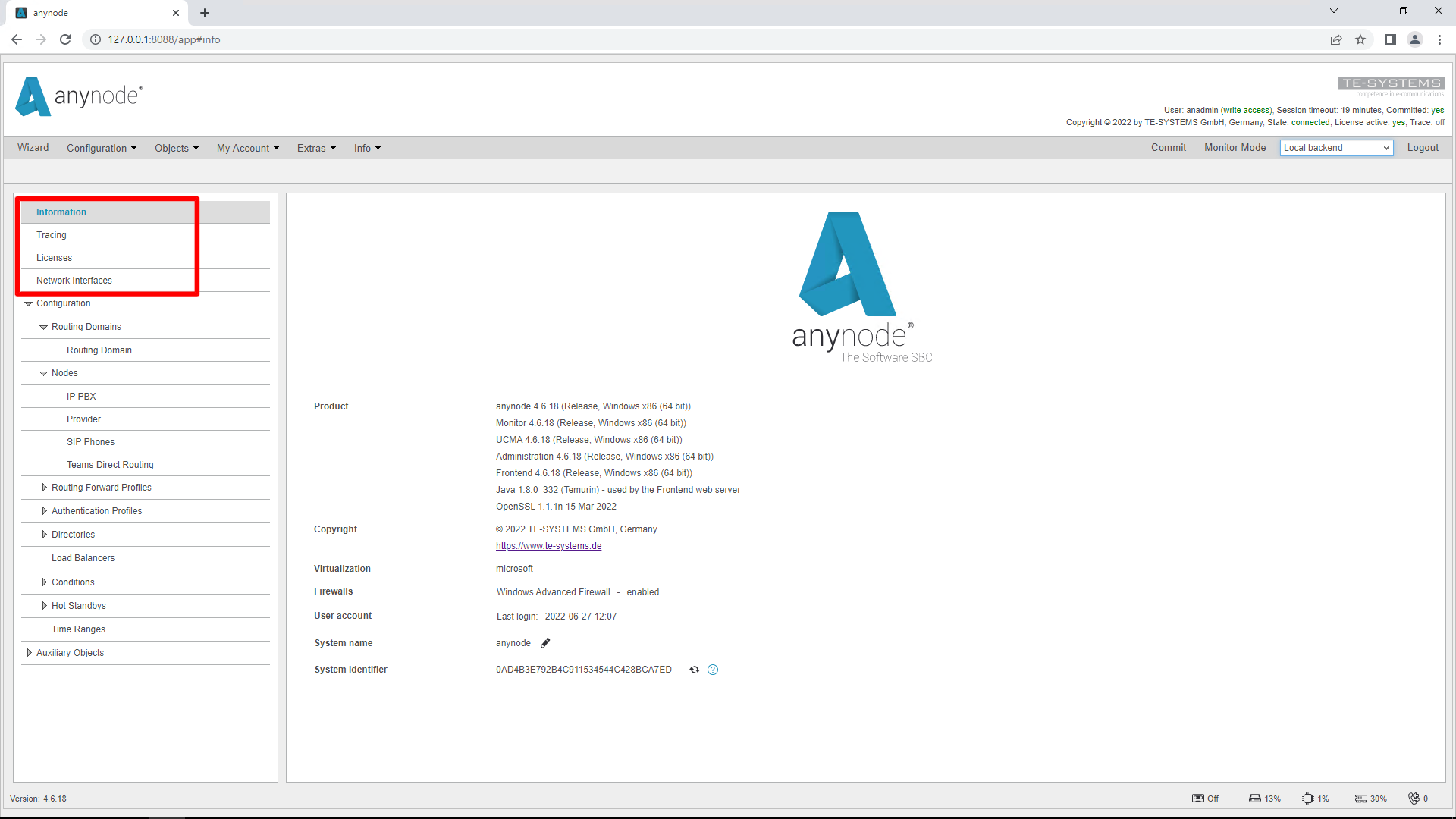
Welcome to another anynode video workshop. In this edition, we invite you to sit back and watch how easy it is to set up a hot standby with two anynode instances and an active/passive failover.
With the hot standby feature, you define important rules so that a secondary anynode system can take over in an emergency as part of a “high availability configuration”. Via the graphical user interface of this feature, all conditions for a switchover to the secondary standby system and back can be individually set.
Prerequisites
To successfully configure a hot standby, you need the following prerequisites:
· Two identical anynode versions 4.6 or later, installed on a primary and secondary system, and located on the same network.
For a Hot Standby, you need to perform 3 important steps:
· Add a local backend connector to the secondary system.
· Add a remote backend instance to the primary system
· Set up the hot standby between the different anynode instances
In our example, we will perform a replication of the primary system configuration to the secondary system.
Add Backend Connector
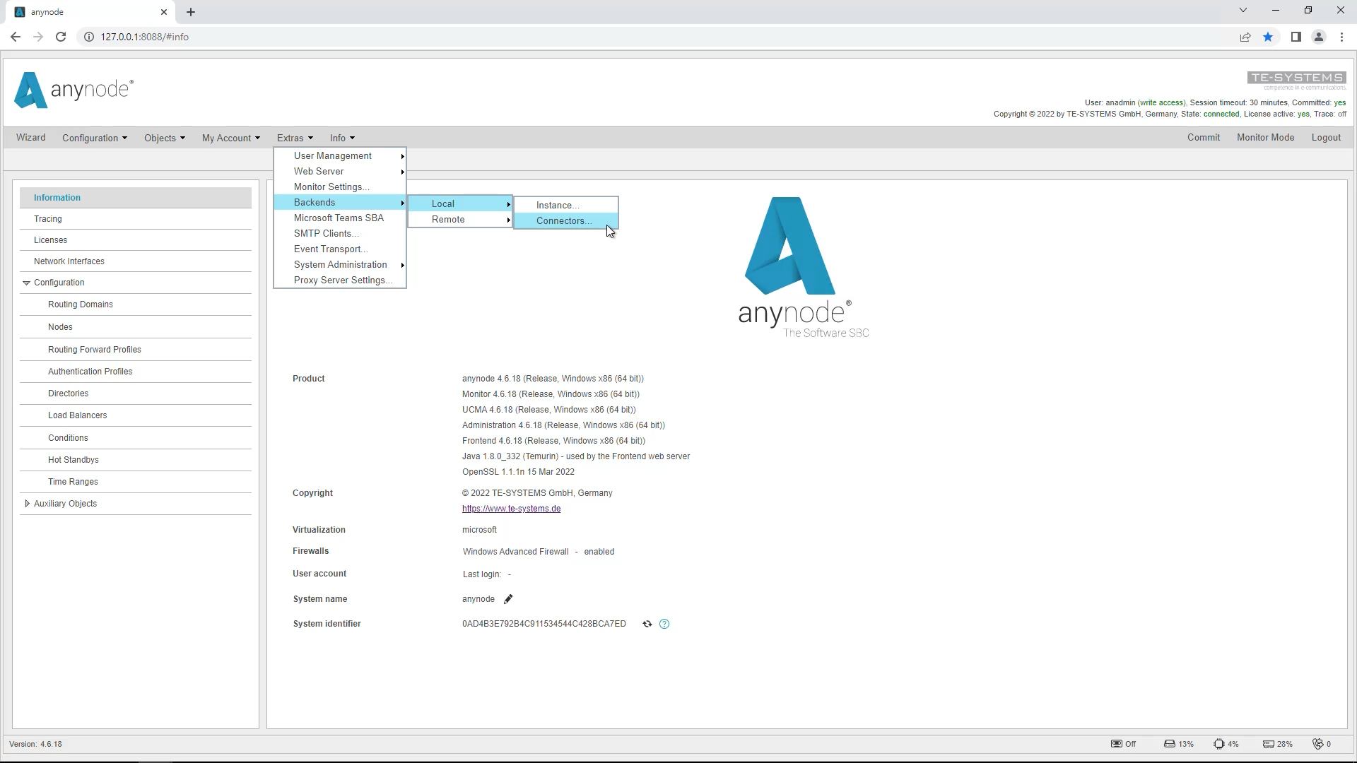
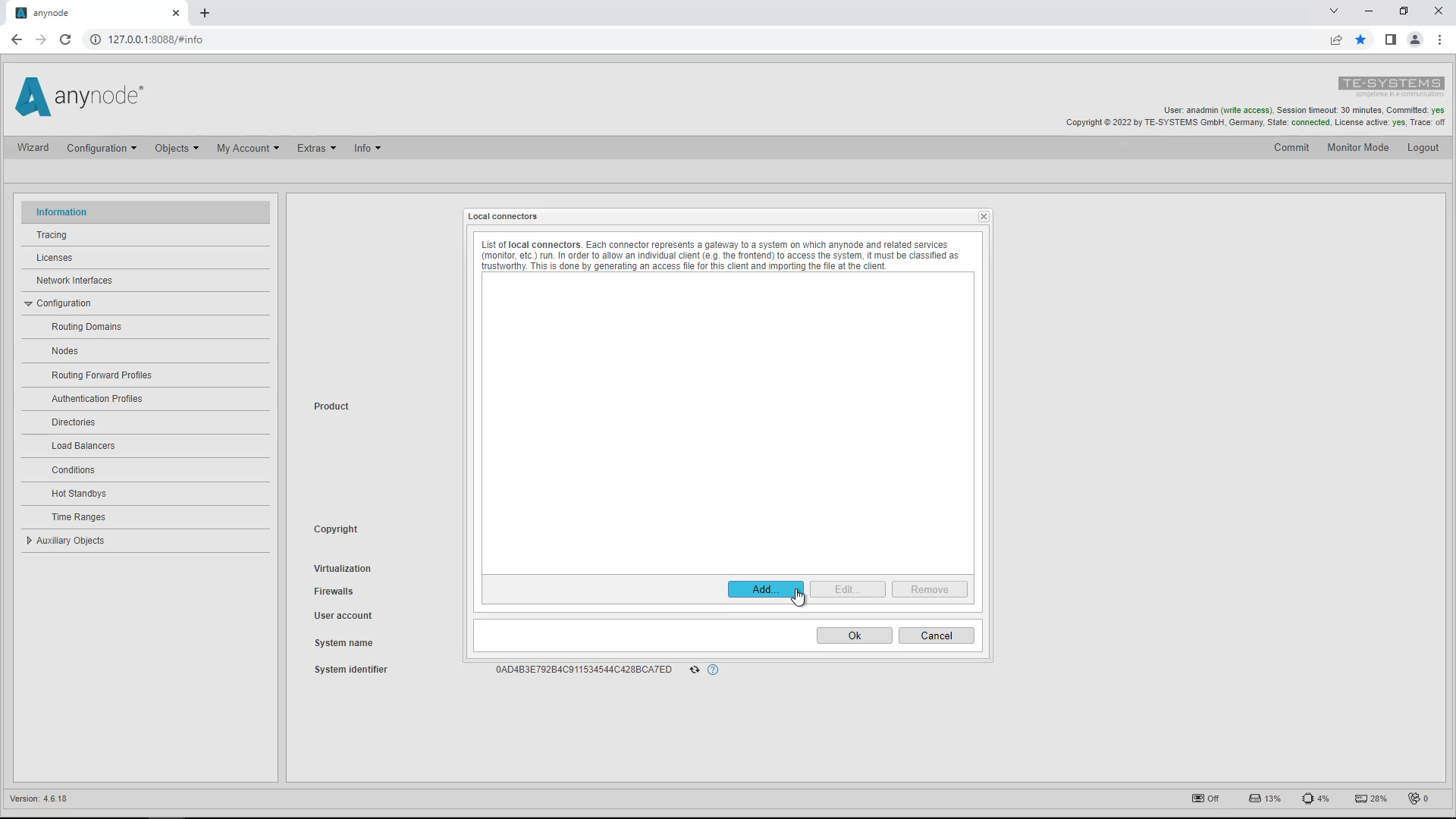
We start on the secondary system and add the local connector there. In the “Extras” menu click on “Backends”, “Local” and “Connectors”. Click on “Add” to add the local connector. The “Connector Assistant” will open.
Click on “Add” to add the local connector. The “Connector Assistant” will open.
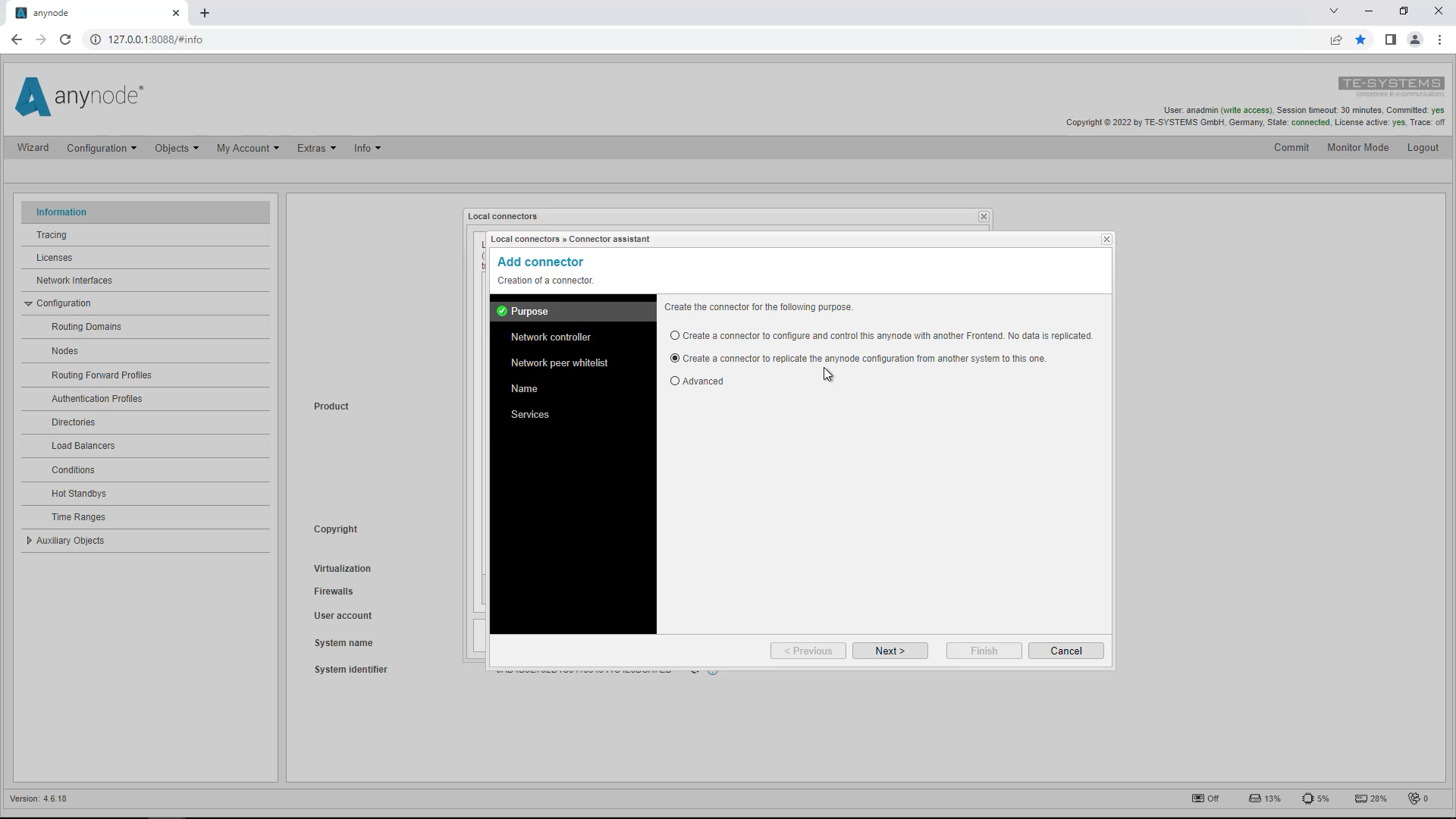
You now have the option to select the purpose of the connector, which will later be created as a backend definition file, downloaded, and imported into the primary system.
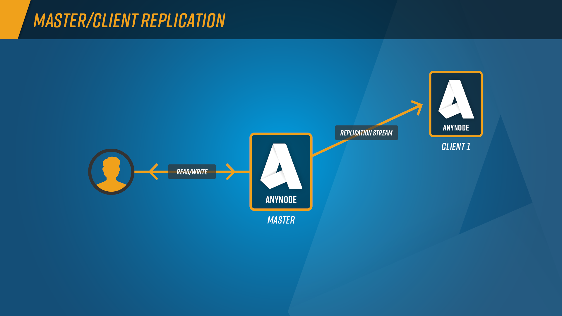
The first option creates a connector that configures and controls this anynode with another frontend. With this option, there is no replication from the primary anynode, but only on explicit instruction.
The second option creates a connector that replicates the anynode configuration from another system to this system. Both systems are then always synchronous in configuration. In our example, we choose the second option.
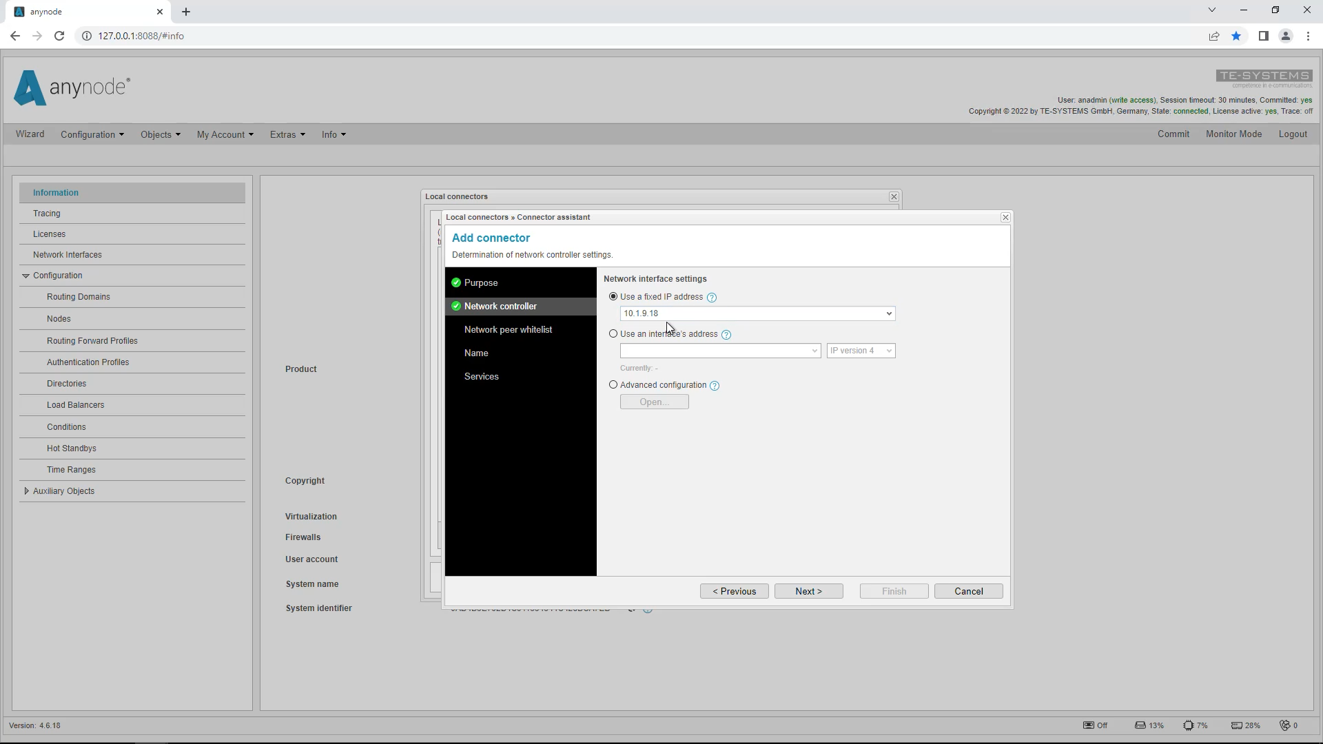
For Network Controller, select the local IP address or network interface to be used for replication.If you are using a static IP address, you can select “Use a fixed IP address” or the desired network interface. If your network configuration is dynamic, you should select “Use an interface’s address “. anynode uses the IP address assigned to a network adapter. Changes to the assigned address are tracked and the IP address to use is updated accordingly. Use the drop-down menu to display the fixed IP addresses. In our example, we select the address 10.1.9.18
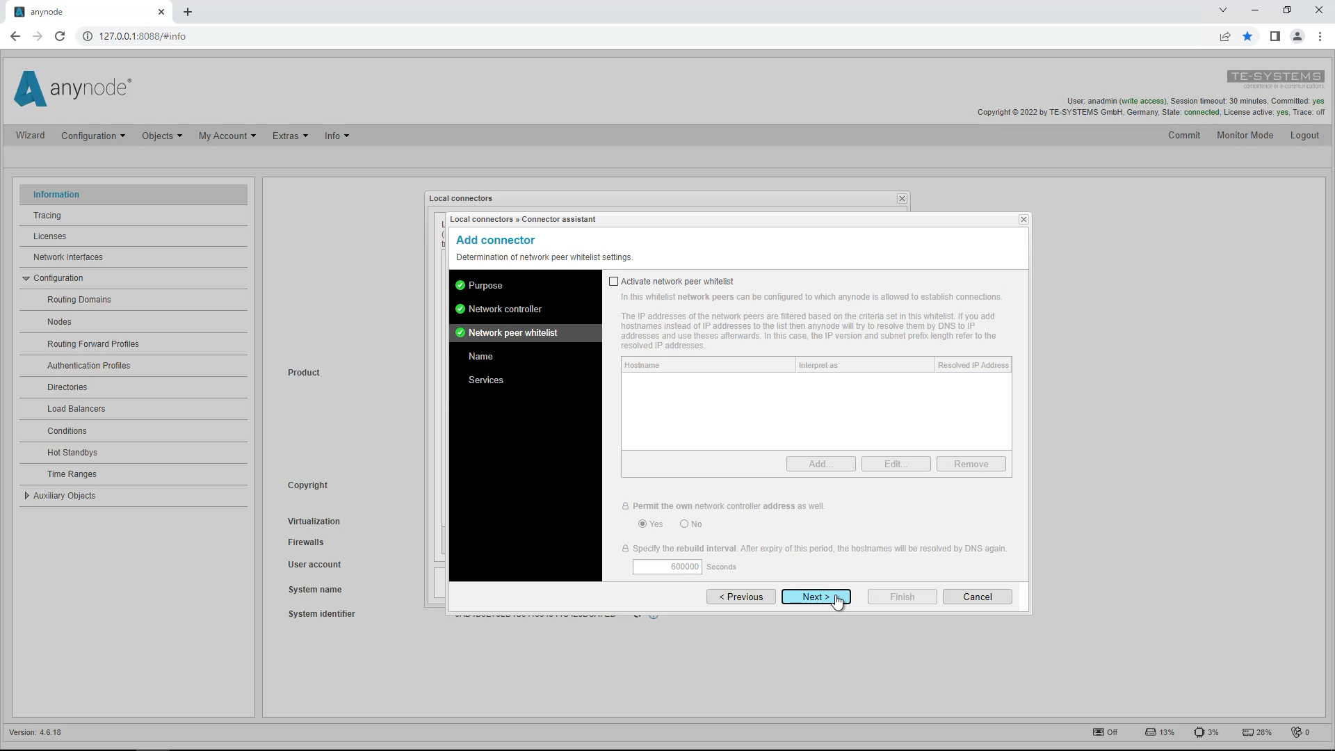
For security reasons, we recommend that you also restrict access via the whitelist, since the backend definition file to be exported later will allow anyone who owns the file to access the system. Therefore, enter the IP address of the primary system here. The other network-specific settings are only necessary in special cases. In our example, we skip the whitelist.
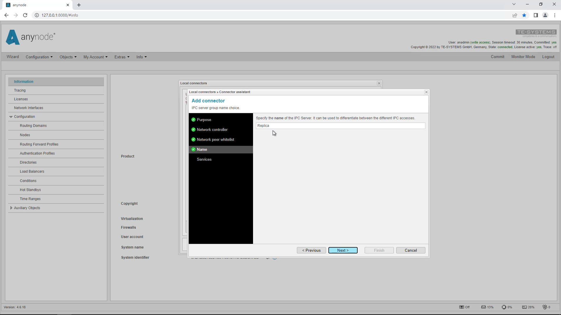
Select the name of the secondary system here. This name will be used later to distinguish and display the secondary system in the primary anynode. In our example, we accept the name “Replica” suggested by the assistant.
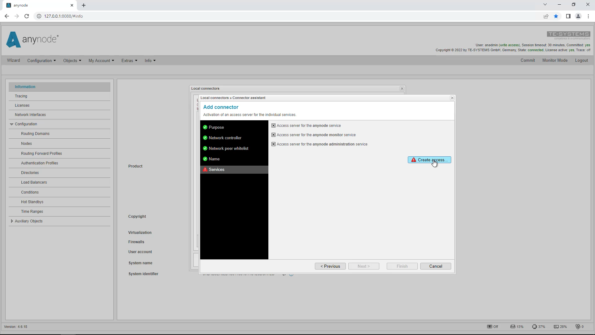
Activate all access servers for the individual anynode services. The wizard already sets all hooks here. This may take a few seconds. Click on “Create Access”.
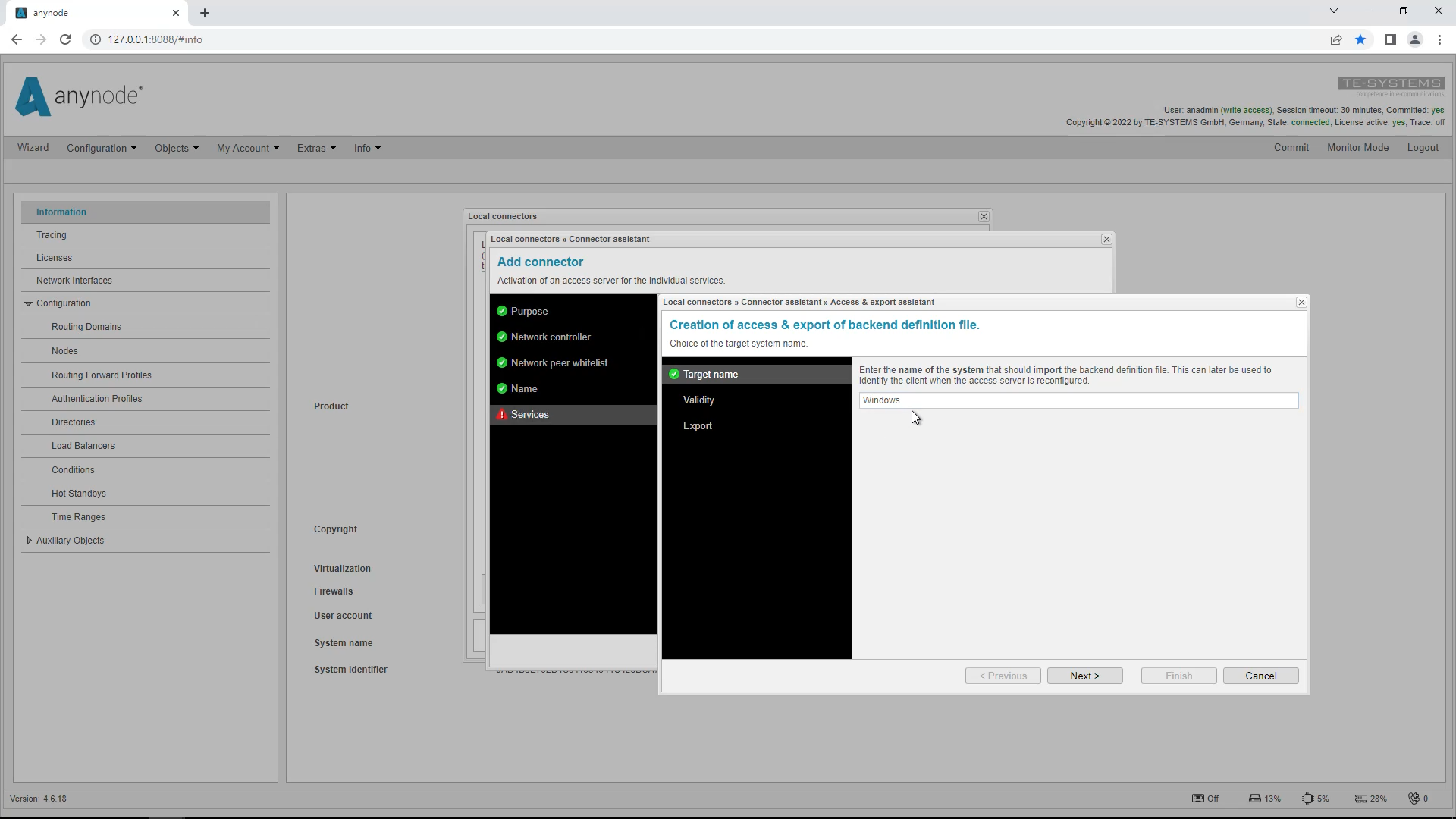
The “Access & Export” wizard opens. Now the settings for the target system are requested, which are necessary for the creation of the Access file. Enter the name of the primary system into which the file is to be imported later.
In our example, we choose the name “Windows” because the primary system runs on Windows and the secondary system on Linux.
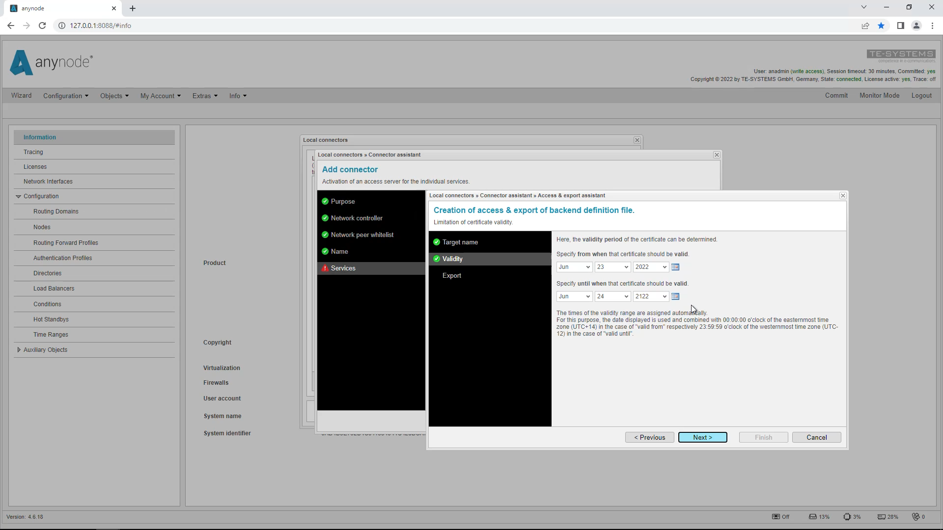
The “Validity Period” defines how long the self-signed certificates for the encrypted channels are valid. The default range is set to 100 years. Accept the suggested default values.
The created backend definition file (*.xzbackend) can be exported and imported to another frontend. The file contains access information for anynode and related services (monitor, etc.) Click “Export” to download the access file. Save the file for import on the primary system and click Finish. Make sure you exit the Connector Assistant now by clicking “Finish”.
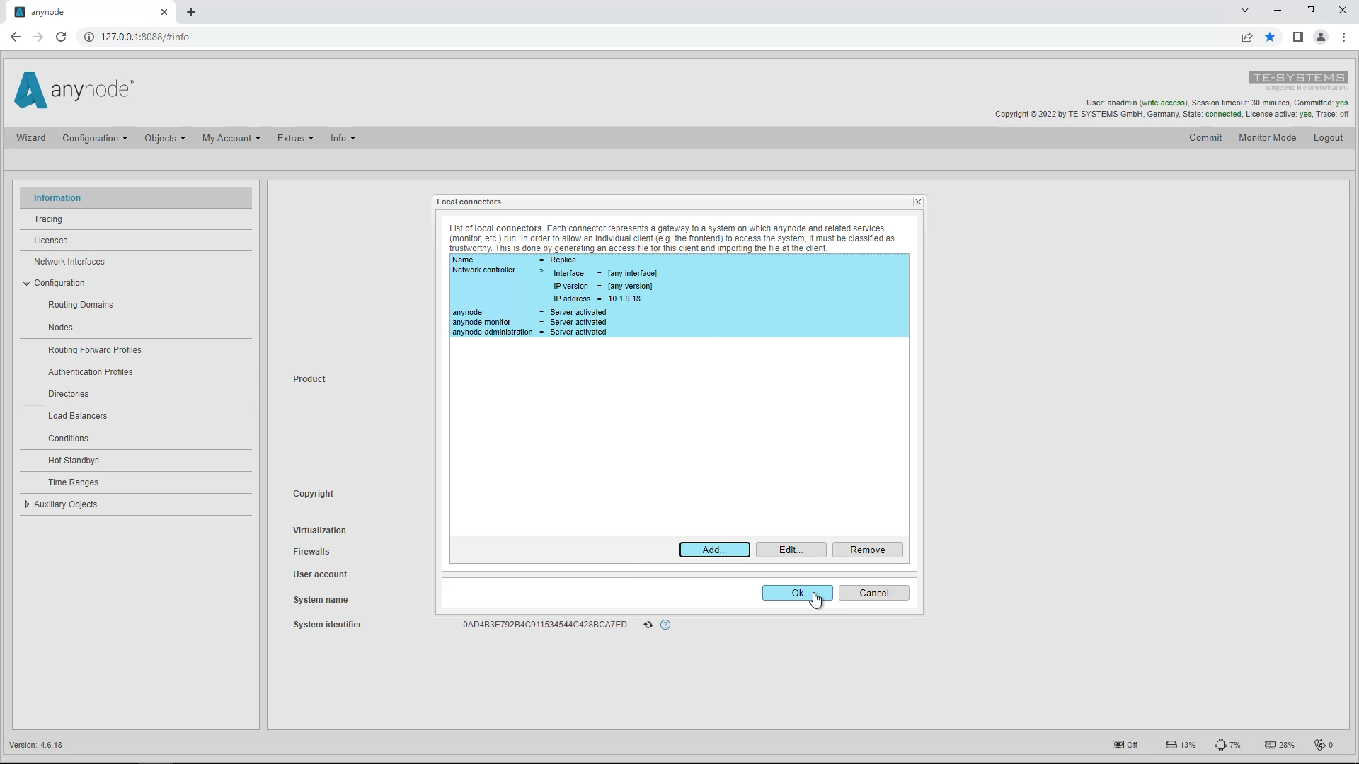
An overview of the local connector you just created is displayed. Click on “OK” to close the dialog.
Add Remote Backend Instance on primary anynode System
We now switch to the primary anynode system. Here we have prepared a ready configuration with different nodes. Later, this configuration will be replicated to the secondary system.
Now we add the exported backend connector to our primary system.
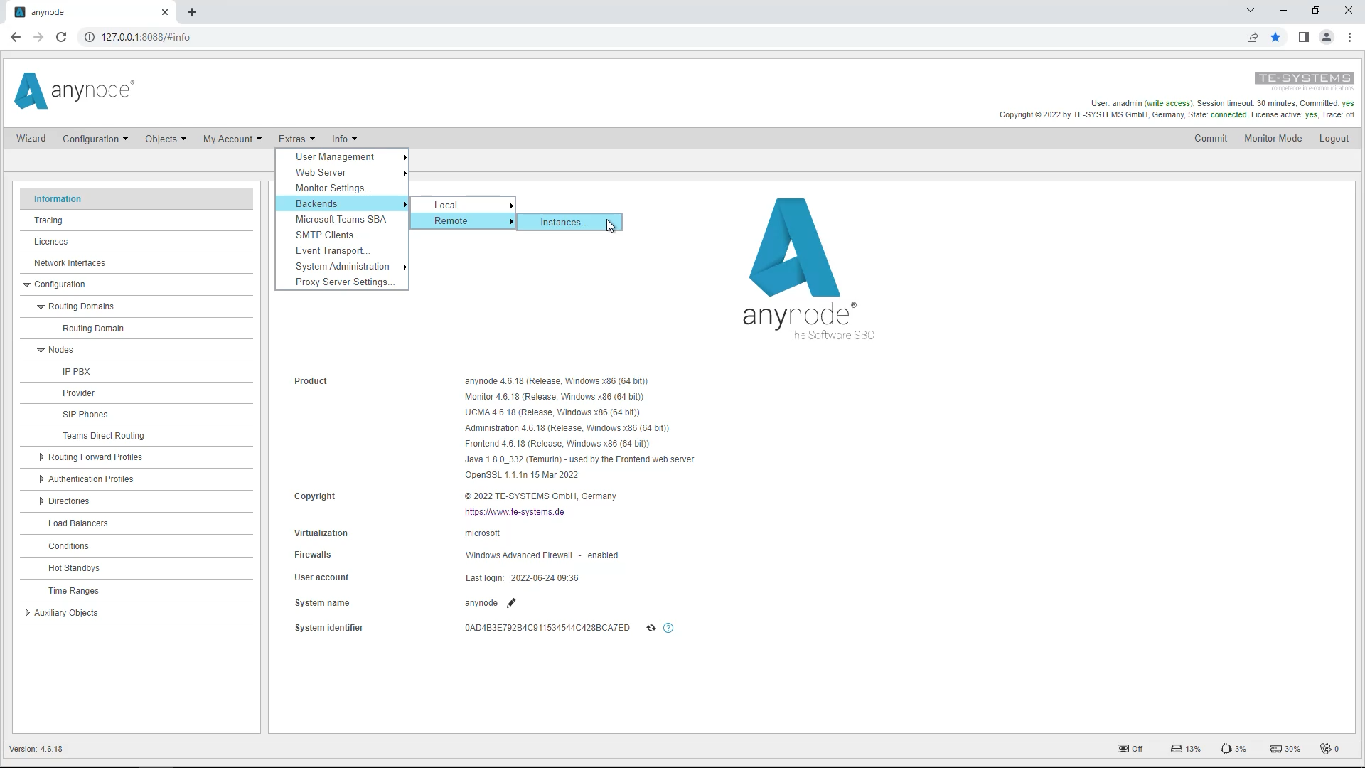
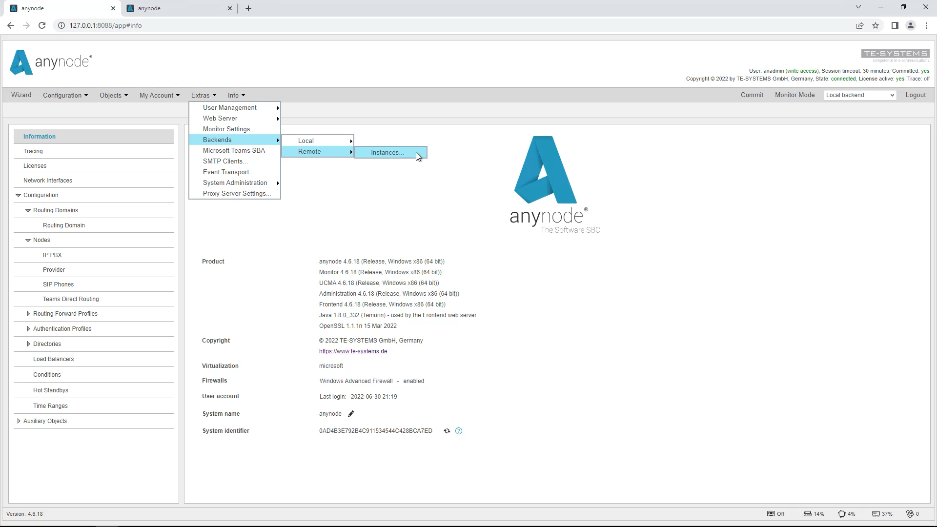
Go to the “Extras” menu and select “Backends”, “Remote” and “Instances” in your primary system.
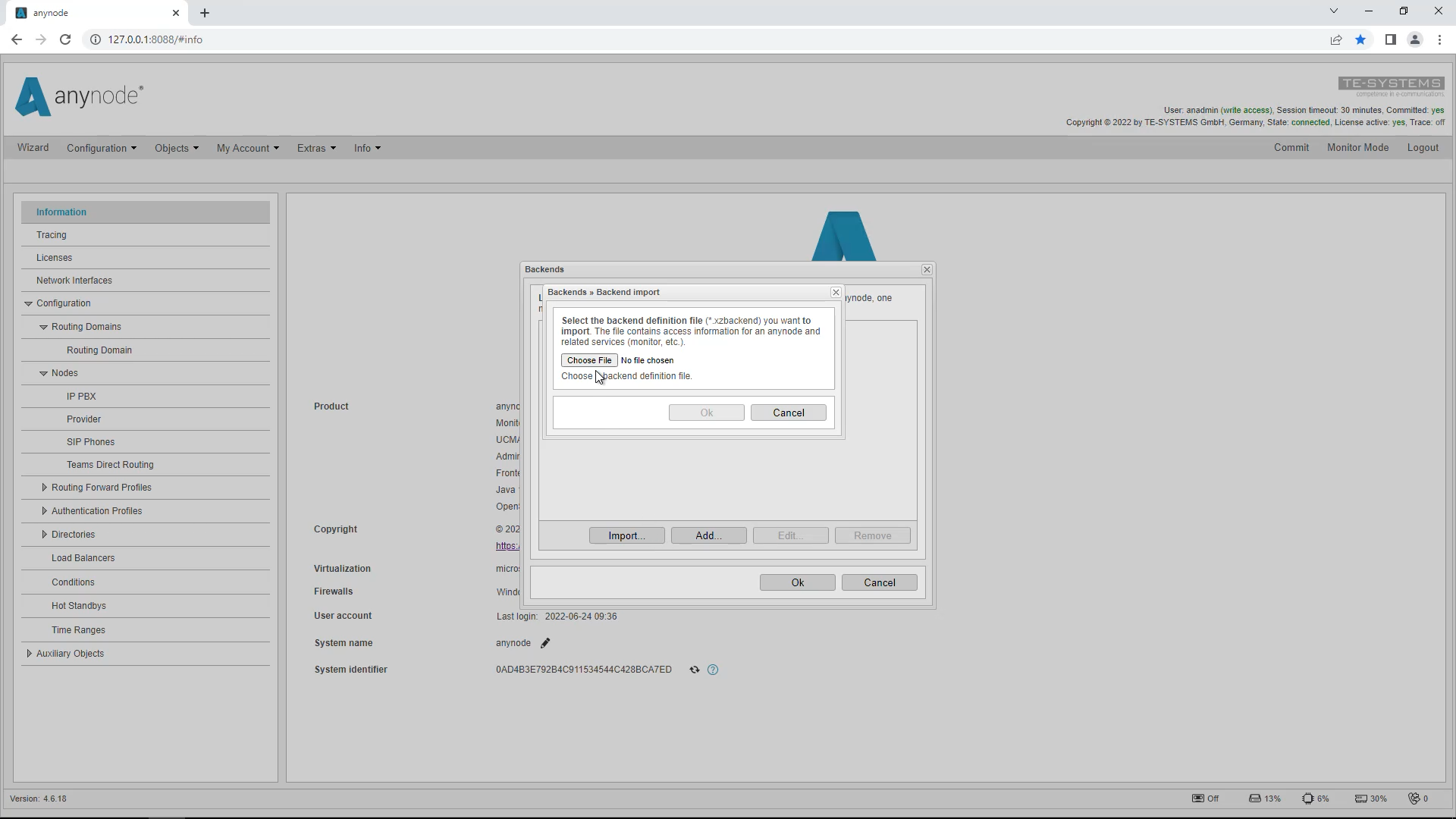
Select “Import” and import the backend definition file you generated earlier.
Then click “Ok”.
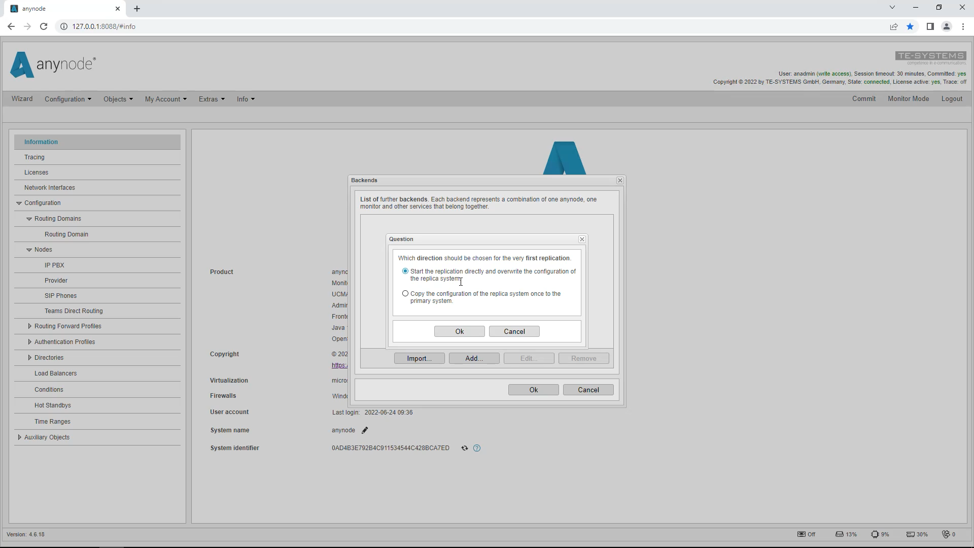
You will now see the query dialog for the direction of replication. The upper option starts the replication process directly towards the secondary system and overwrites an existing configuration there. The lower option can replicate the configuration from the secondary system back to the primary system in case of a total failure of the primary system.
Start the replication directly and overwrite the configuration of the replication system.
Wait a few seconds. You now have the option to switch directly to the secondary system (replica) on the primary system. To do this, use the switch in the upper right area.
Settings per Instance
Please note that the following things are not taken into account during replication and synchronization:
· Tracing settings
· Licenses
· Network card and settings
So you have to license the secondary anynode separately and cannot take over the license from the primary anynode. Basically, everything in the menu tree below the Configuration item is replicated and synchronized. These items cannot be changed on the secondary system.
All items above are used separately on the secondary system, such as the trace function. The network settings must be set separately on the secondary system since each system has its own network settings. To do this, open “Network Interfaces” in the left-hand menu tree on the secondary system. We will go into this in more detail in a moment.
Set up Hot Standby with the Hot Standby Assistant
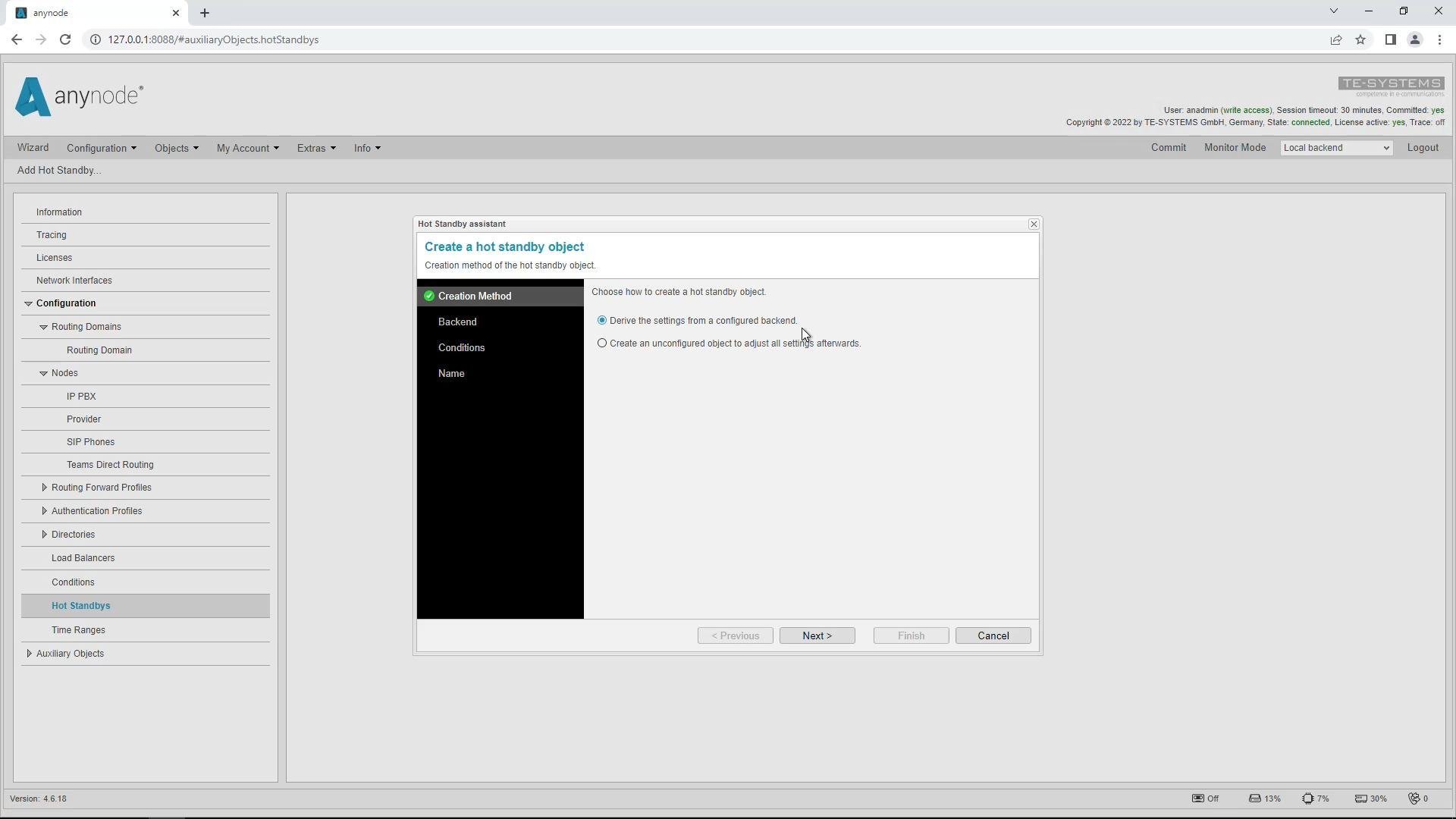
We will stay on the primary system. Go to “Hot Standbys” in the left menu bar and then click on “Add Hot Standby”. The Hot Standby Assistant will open.
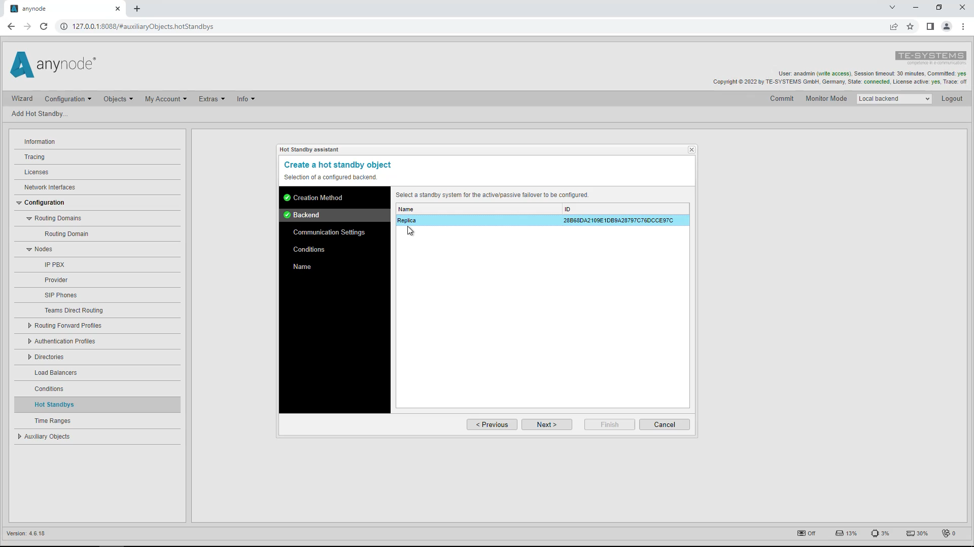
In the first step, you will be asked how to create this hot standby object. The default setting for the “Creation Method” is “Derive the settings from a configured backend” and is recommended if you have already configured a backend, in our case a secondary system. The second method only creates a hot standby object, to which a secondary system can be assigned later.
Select the name of the secondary system as the backend. We called this “Replica” earlier.
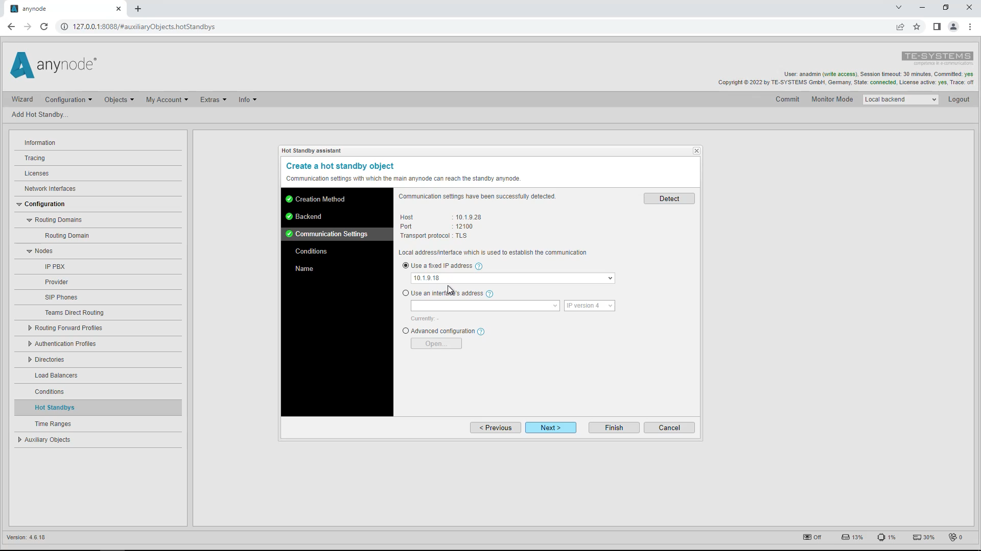
Accept the network settings suggested by the wizard.
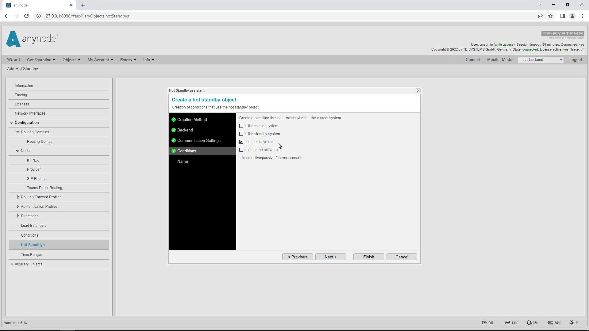
When setting up a hot standby system, the associated conditions are created, which can be used per node to change the way the node works. In our example, we now only use the condition whether a system is the active one. We, therefore, deselect everything except “has the active role”, because in this master/client replication we only decide whether a node is active according to the active role.
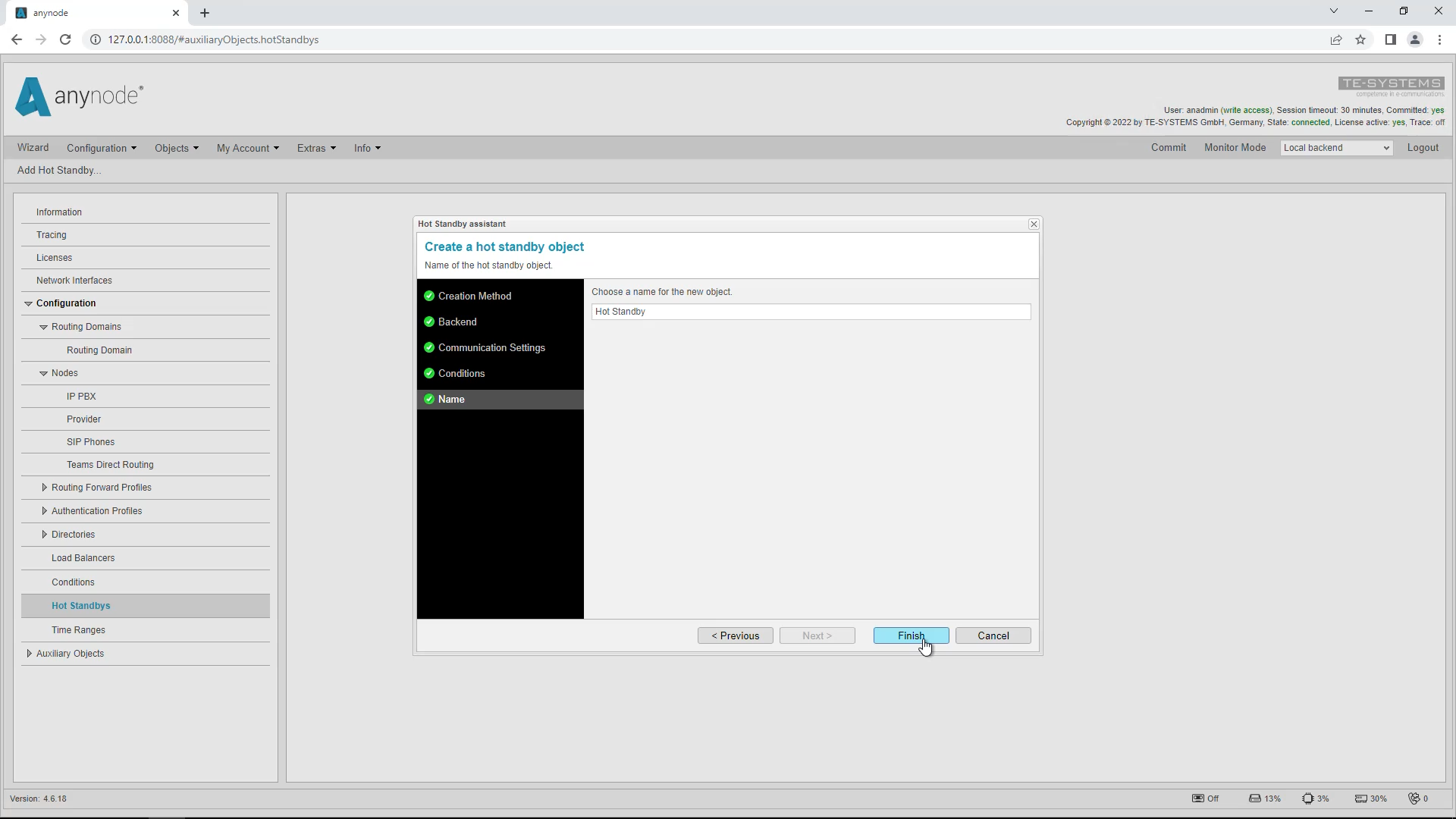
The name of this hot standby object is, as always, freely selectable. We will use the name suggested by the wizard.
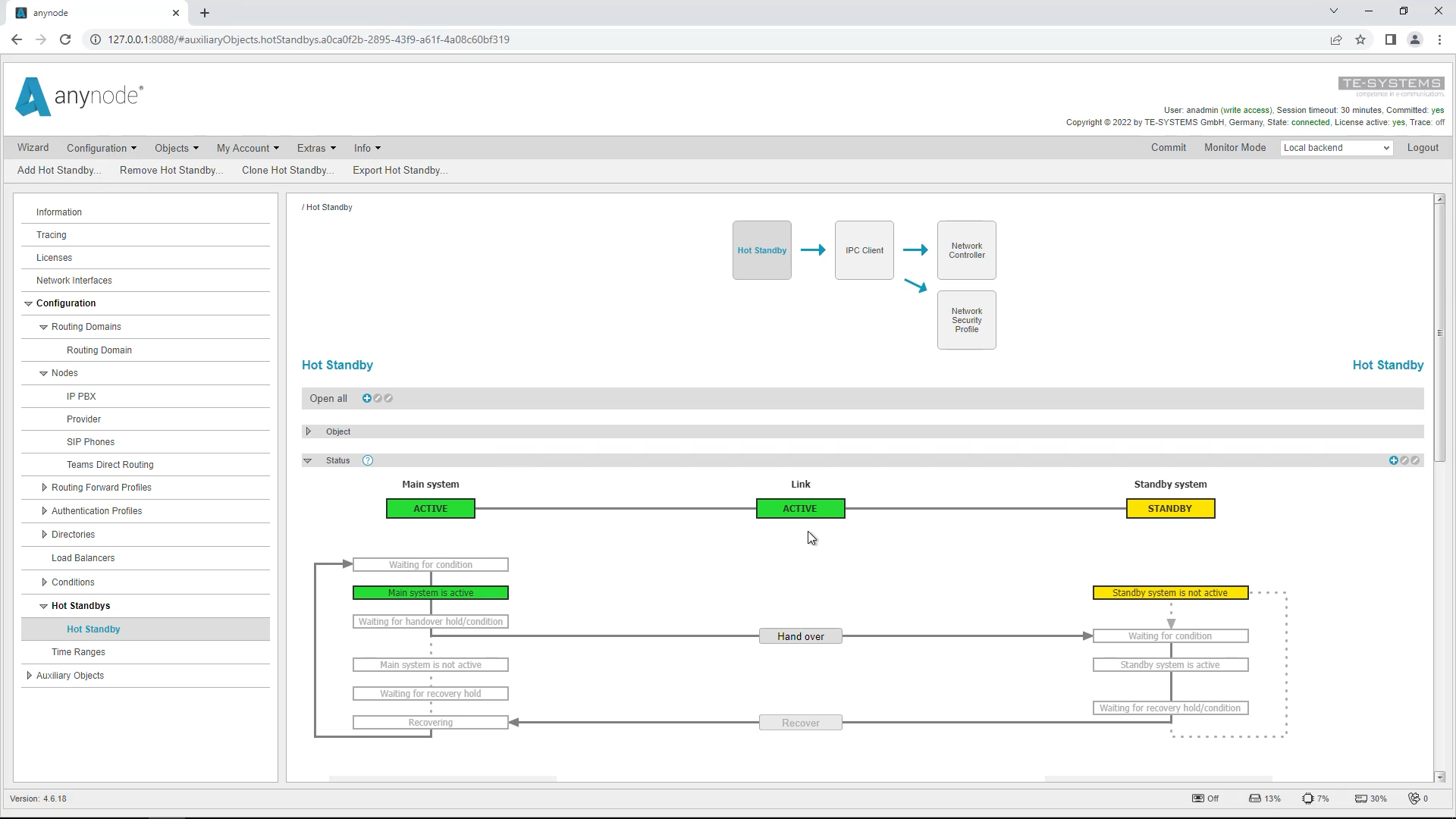
Apply the changes with “Commit”. The Hot Standby graphical user interface now shows you the current operating status.
Configure Network Controller
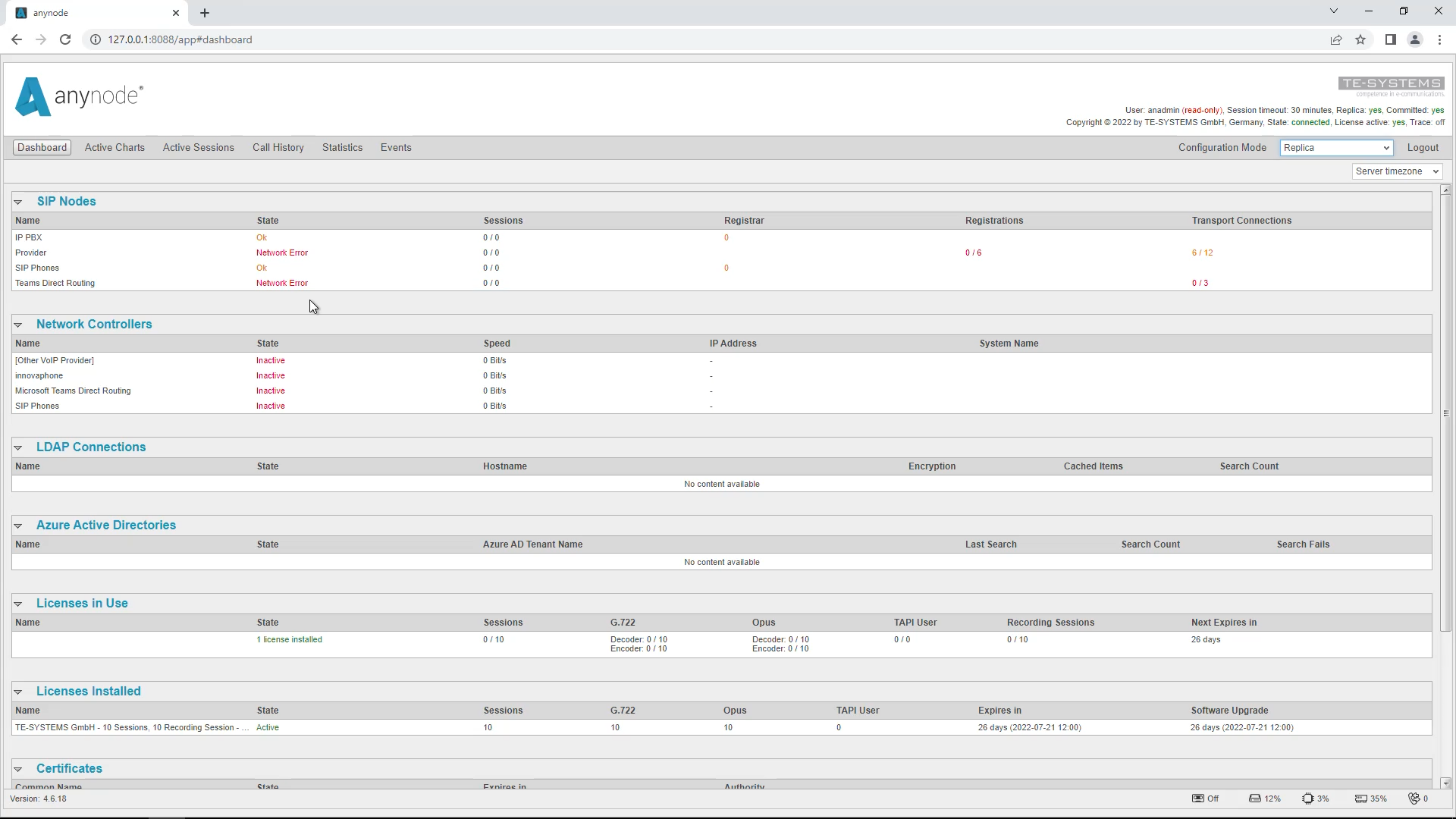
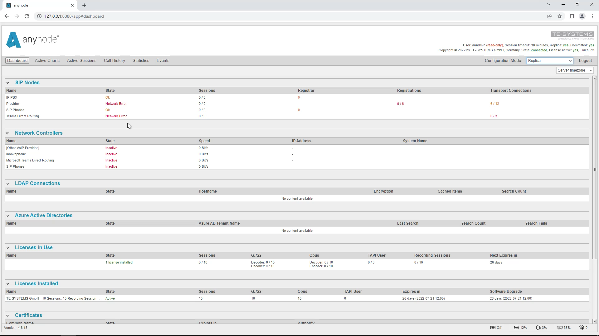
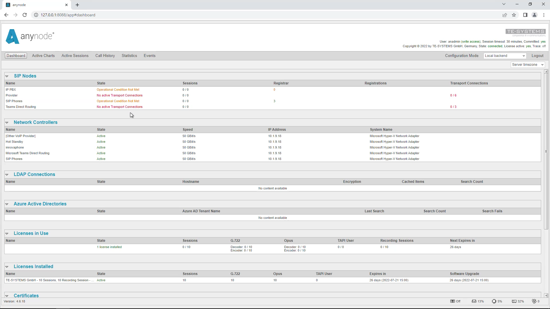
At the moment, we only have a replica. To get it working properly, we still need to do a few things. If you are on the replica system and go into monitor mode, you can see that something is not working properly.
Right now, the replica system is trying to use the same network interface as the master system because all the settings are just copied. We want to change this so that each machine uses the correct network interface. To accomplish this, you need to edit the network controller of each node on the master system. These settings are then replicated to the replica system.
IP Address Configuration
Method 1: Pivoting IP Address
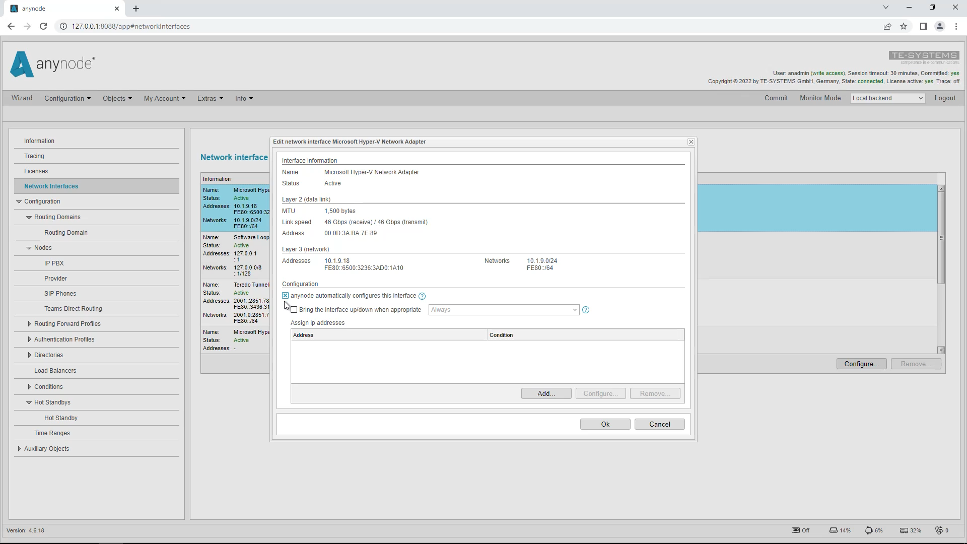
There are several methods to set the IP address depending on the topology used. The first method we would like to introduce relies on a pivoting IP address. On the primary and the secondary system, you can edit the menu item “Network Interfaces” individually.
Start with the primary system. Select the interface that your nodes use, in our case it is the Microsoft Hyper-V Network Adapter. Click on “Configure” to edit it.
Activate
“anynode automatically configures this interface”.
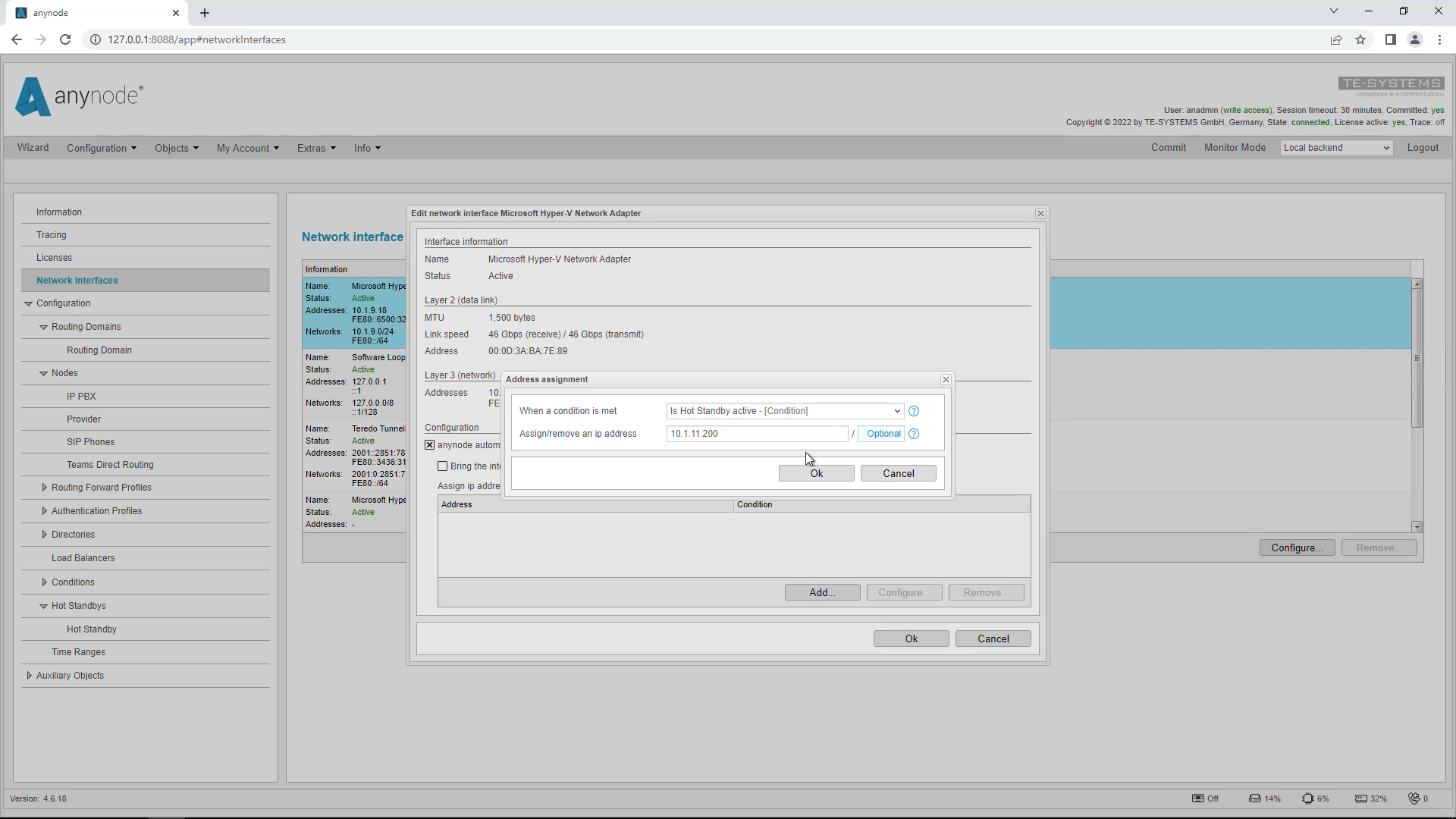
Do not enable the option “Bring the interface up/down when appropriate” as other IP addresses may be in use on the network adapter. Click on “Add” in the IP address list. Select the condition “Is Hot Standby active”. This condition is always set to “true” on the master system, unless the system is in maintenance mode. On a client system, the condition is always “false” as long as the master system reports that it is active. You must also set a static IP address in the same address range as the two systems. In our case, this is 10.1.11.200.
Switch to the secondary system and make the same settings there.
Then switch back to the primary system. The following settings are always done on the primary system.
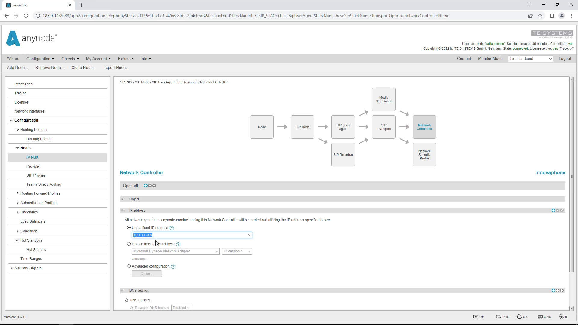
You must now change the IP address set in the “Network Controller” object in each node to “Use a fixed IP address” and enter the IP address used earlier in the network interface, in our example 10.1.11.200. Do not forget to confirm the entries afterward with commit.
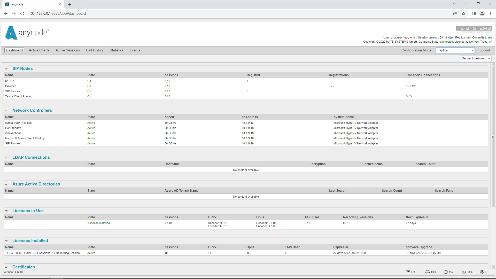
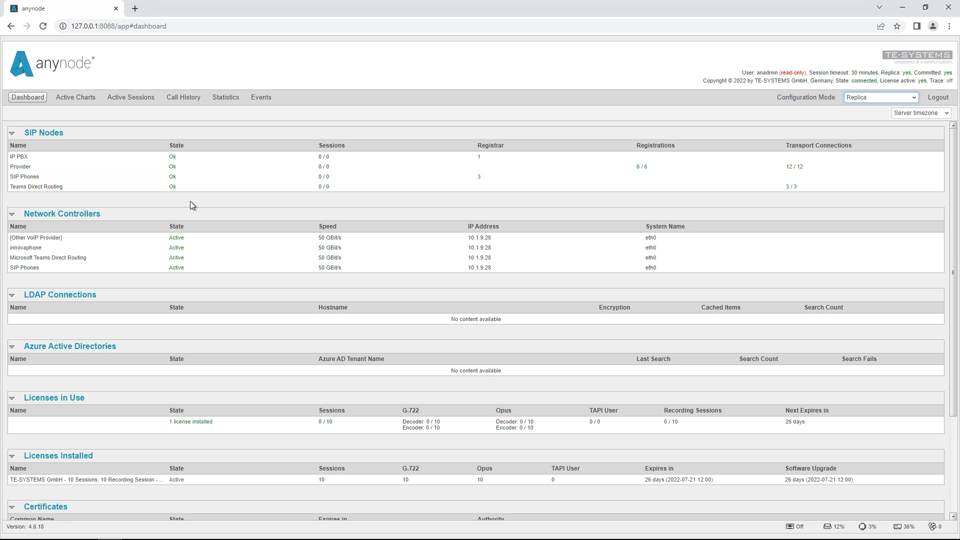
Observe the dashboard displays of the nodes on the primary and secondary systems. The nodes on the primary system should now be green and on the secondary system red, since the primary system is still active. So method 1 automatically creates an active/passive system.
IP Address Configuration
Method 2: Different IP Addresses
In this method, the systems are assigned different IP addresses. Basically, the following settings are made on the primary system and are only possible here. You must make the settings in each node.
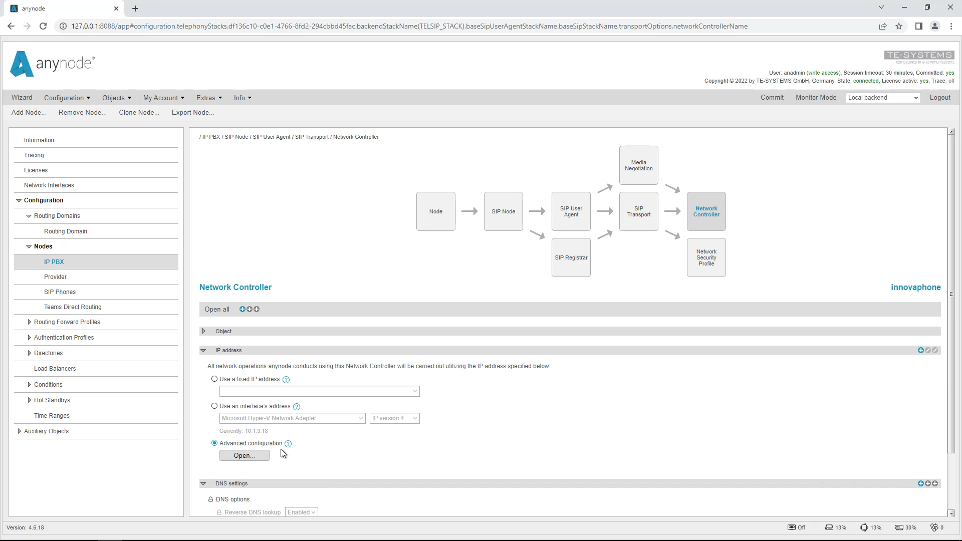
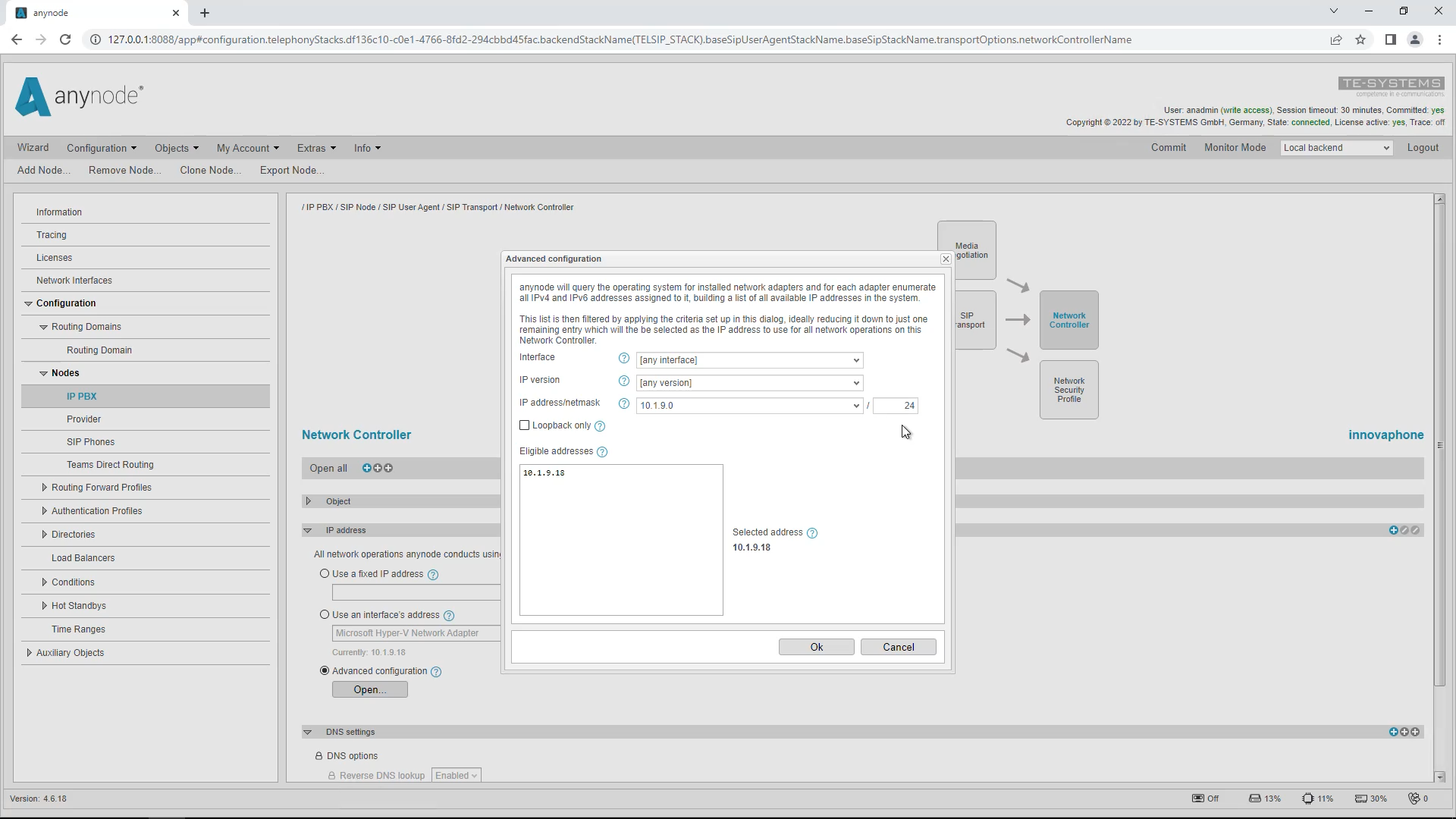
Go to the “Network Controller” object in the node and change the setting to “Advanced Configuration” and click “Open”.
For Interface, select “[Any Interface]”. The IP version depends on the network environment. At “IP address/netmask” enter either the IP address of the network interface to be used or the network address of the network. This is 10.1.9.0.
In the input field for the netmask, you enter the network mask of the network you are in. In our example, this is 24.
Observe the dashboard displays of the nodes on the primary and secondary systems.
The nodes on the primary system should now be green. On the secondary system, the nodes should also be green now. So, with method 2, an active/active system is always created automatically.
Advantages and Disadvantages of the Methods: Method 1
We would now like to present the advantages and disadvantages of the 2 methods for IP address configuration.
Method 1 has less configuration effort because you only have to specify an anynode on other systems. However, a system set up this way can usually only be maintained outside of business hours, since the remote machine pulls away the IP address of the primary system and immediately terminates existing sessions when the main machine goes into maintenance mode. For cloud service providers, it is generally problematic if the IP address used is to be accessed from the public network.
An active/passive system is automatically created with method 1.
Advantages and disadvantages of the methods: Method 2
With method 2, each system has its IP address, so when the main system switches to maintenance mode, the current sessions can still exist and slowly expire while the backup system can already accept new calls. However, there is a higher configuration effort here, because you have to set up several anynodes in the systems. Not every provider and not every system can handle multiple IP addresses.
When using method 2, an active/active system is automatically set up. If you want to set up failover, the following chapter is relevant.
Set up Operational State Condition
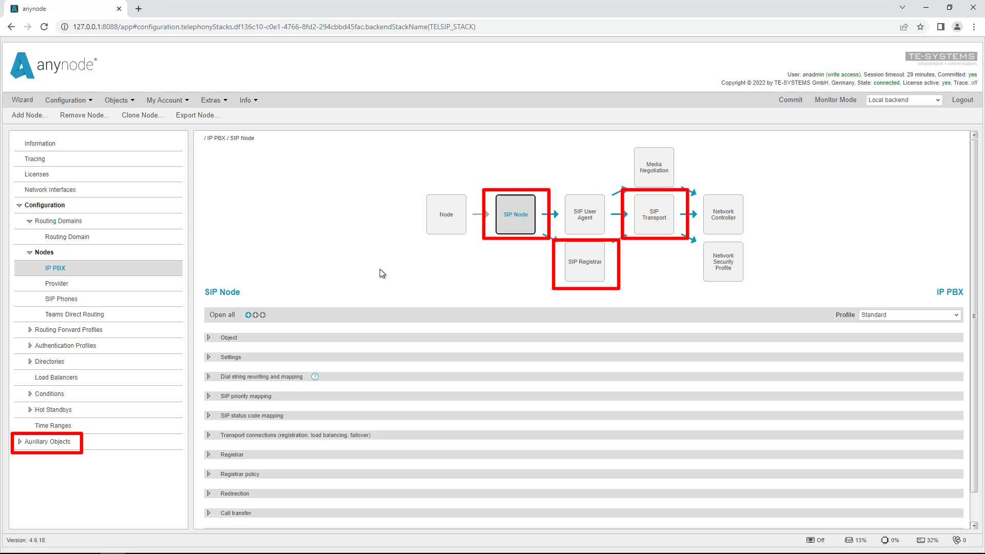
In the next step, we set up the nodes to be in passive mode on the replica machine until the master machine is in maintenance or has no connection due to system errors, for example. We have up to 4 objects where we can set this up.
Each of these objects has its own purpose. These are:
The SIP Node object
When shutting down at the node level, all outgoing traffic is stopped directly. This means that the node is administratively shut down and not considered for routing or anything like that.
The SIP transport
SIP transport should be turned off so that no incoming traffic can take place.
The Standard Transport Connection
The Standard Transport Connection should be turned off so that the node does not connect to providers.
The SIP Registrar
which is usually instead of but sometimes in addition to a Transport Connection: You have to disable this one so that the clients can’t connect to this registrar anymore. In our environment, the SIP Phone is set up to connect to the replica server.
In the Nodes, you need to do the following steps:
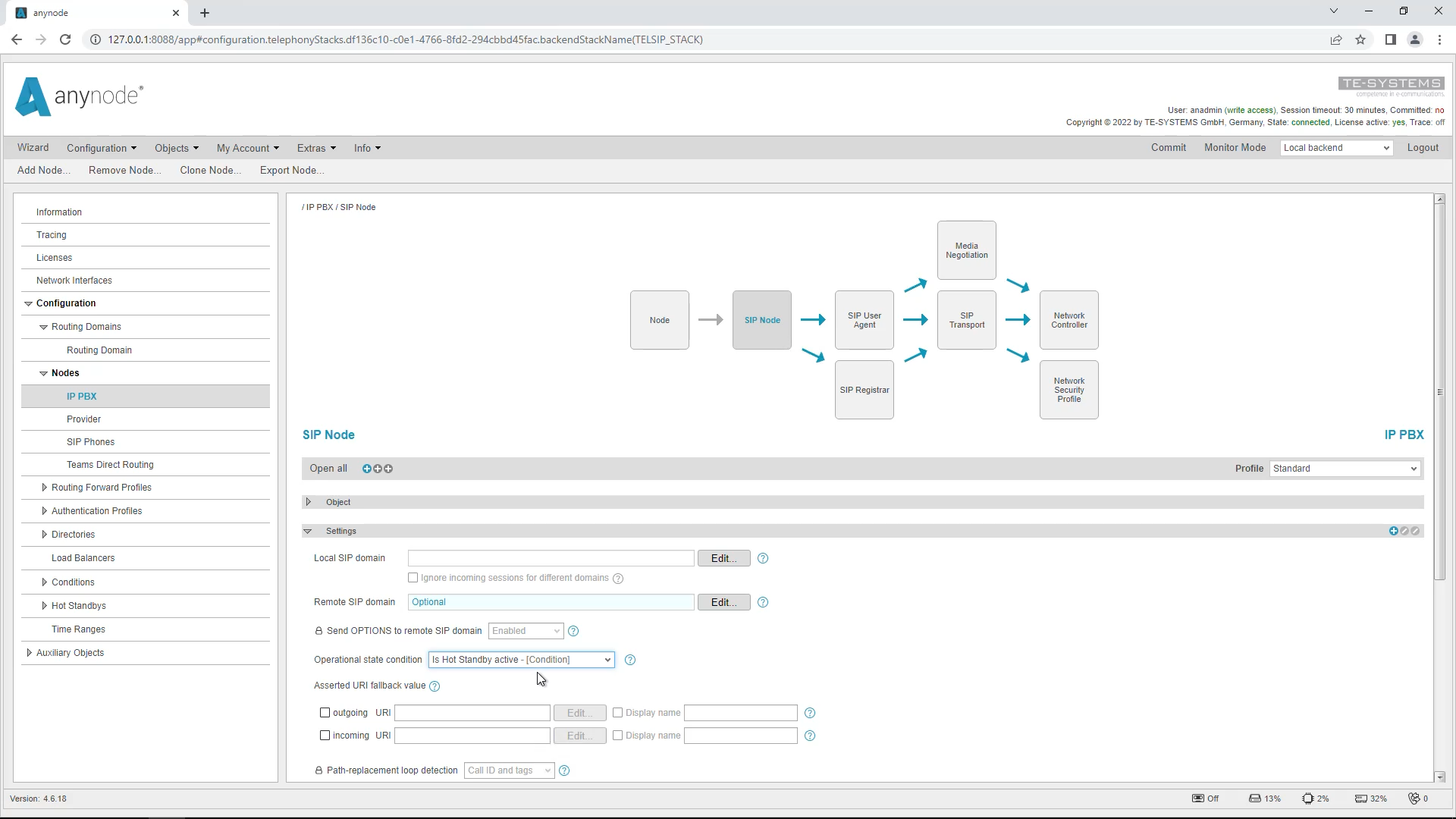
“SIP Node” object
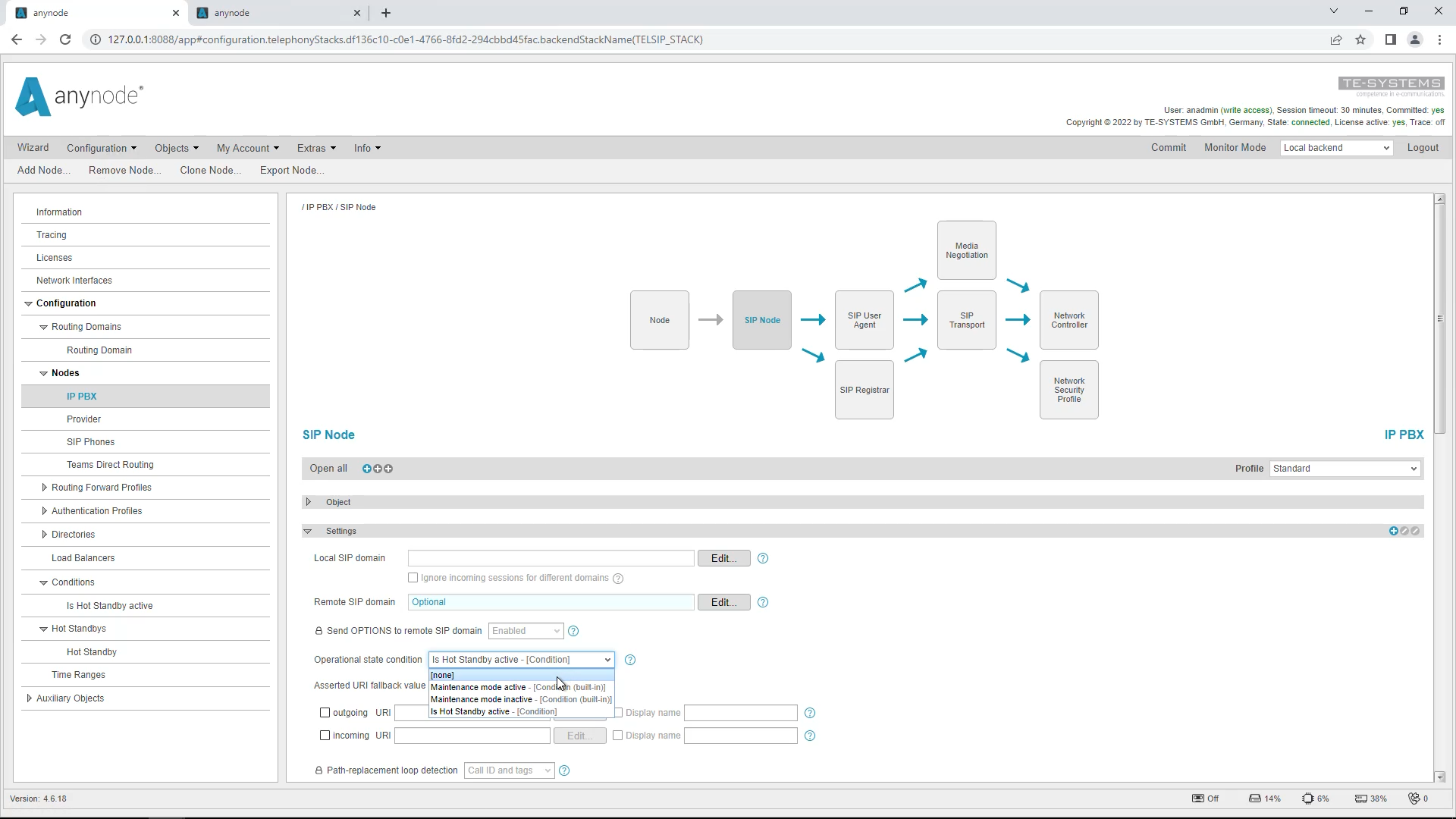
In the “SIP Node” object, go down to “Settings” and select “Is Hot Standby active” as the “Operational State Condition” in the drop-down menu for the Operational State. This is a built-in condition and is true or false depending on whether the system is active or passive.
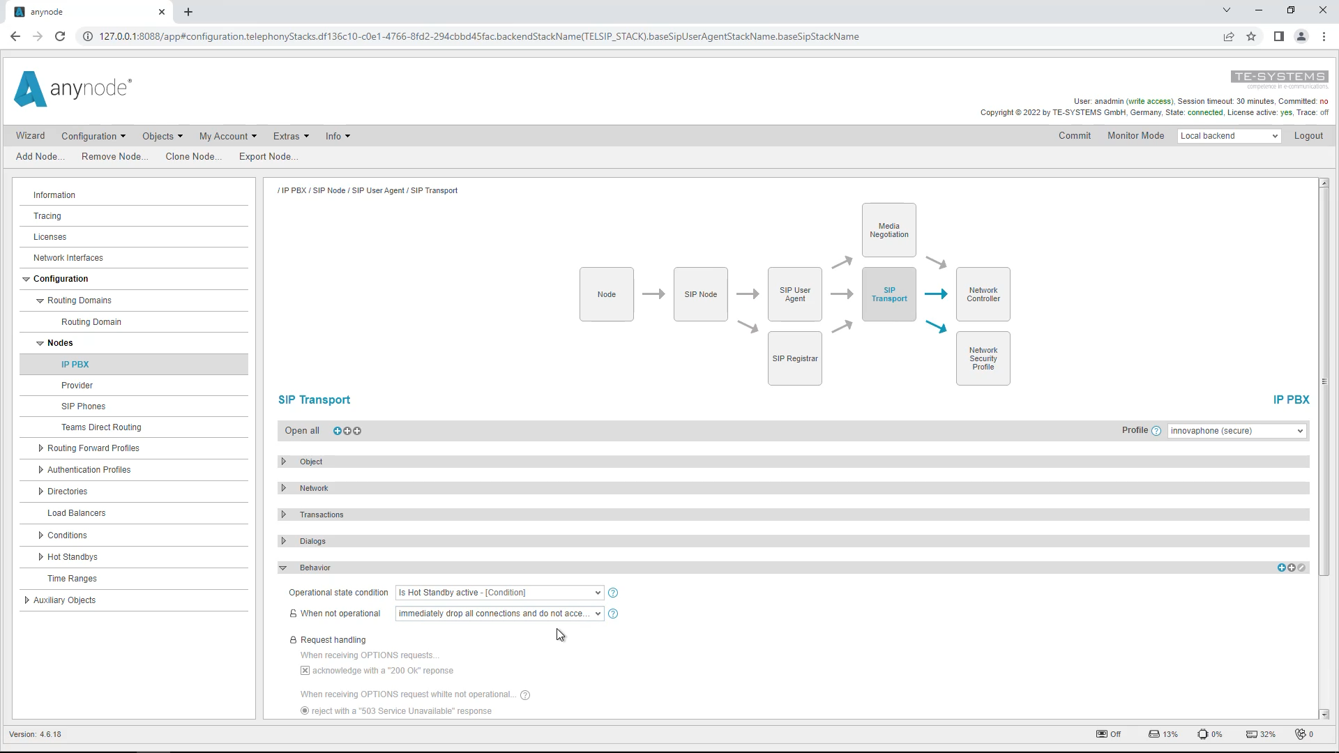
Object “SIP Transport”
Next, in the “SIP Transport” object, under “Behavior”, open the drop-down menu for the “Operational State Condition” for the operational state and select “Is Hot Standby active”. In an active/passive system, we recommend the setting “immediately drop all connections and do not accept new traffic” for “When not operational”. With this setting, active calls are immediately terminated when the active system is changed and no new calls are accepted from the active system. The ports will be closed.
You have to do this in each node.
In our configuration, Transport Connections are present in the provider node.
If you have only Transport Connections, you can do it directly in the node under “Transport Connections”. In our case, we have Load Balancing Connections, so we need to do this in the “Auxiliary Objects”.
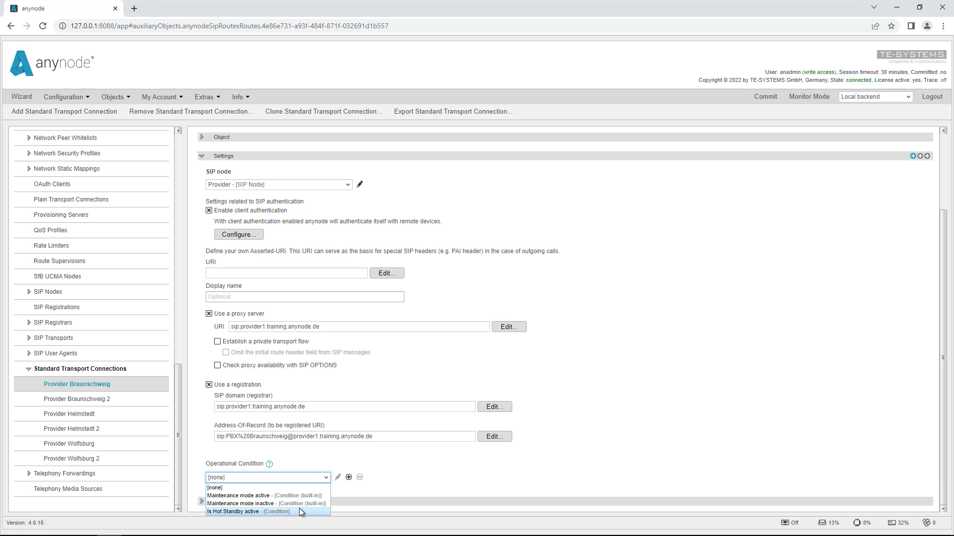
Go to “Auxiliary Objects”, and scroll down to “Standard Transport Connections”. Open these Transport Connections, scroll down, and select the “Is Hot Standby active” option again as the “Operational Condition”. Do this for all the Transport Connections.
Object “SIP Registrar”
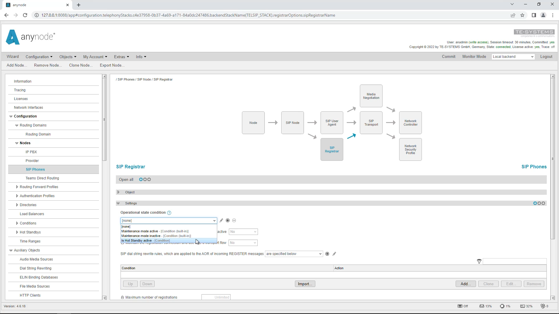
In the “SIP Phones” node, we have a SIP Registrar. Open the SIP Registrar object and under “Settings” select “Is Hot Standby active” again for “Operational state condition”.
In our example configuration, we do the same in the “IP PBX” node.
Hot Standby User Interface
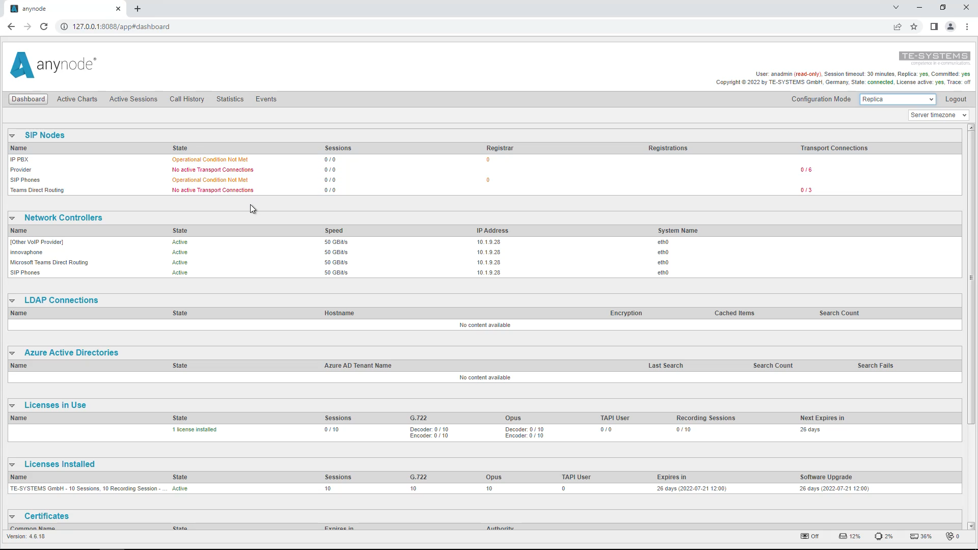
When you are done, switch to the replica’s Monitor Mode again. Now you will see that the nodes were intentionally turned off. When you return to the master system and inactivate it, you will see that the nodes in the replica system are then working.
You can make a system inactive by following these steps:
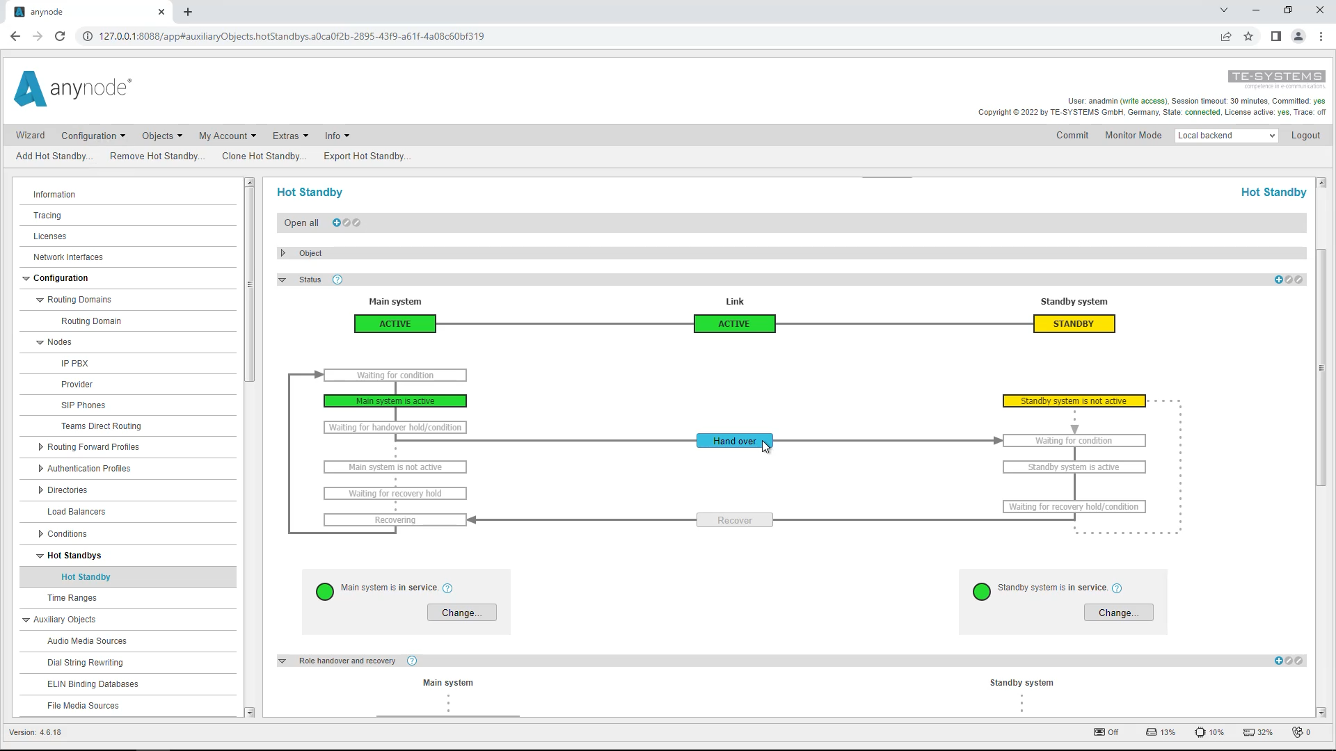
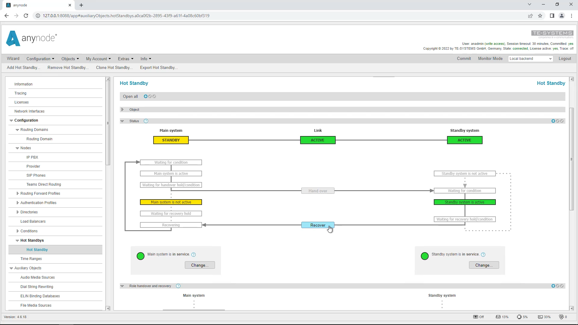
Go to Hot Standby and select Handover to make the replica system active.
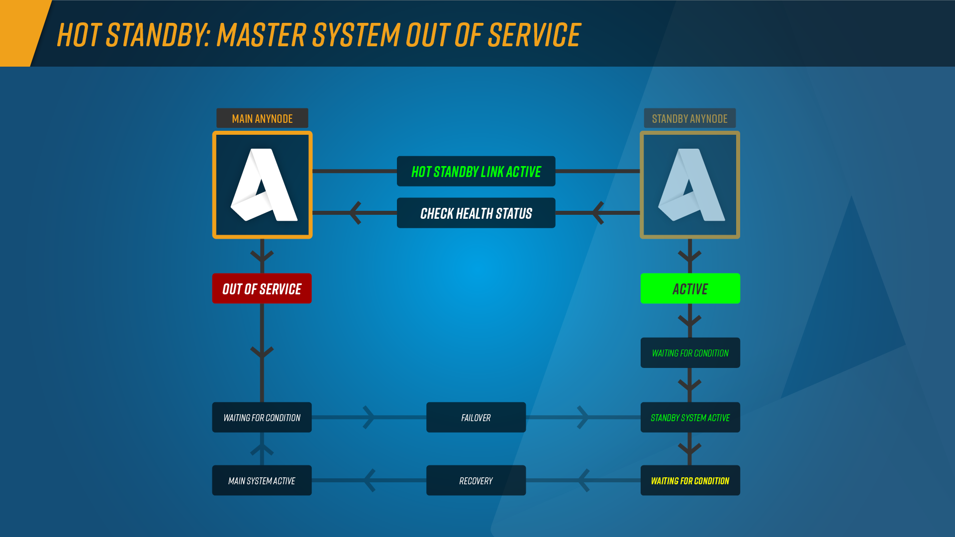
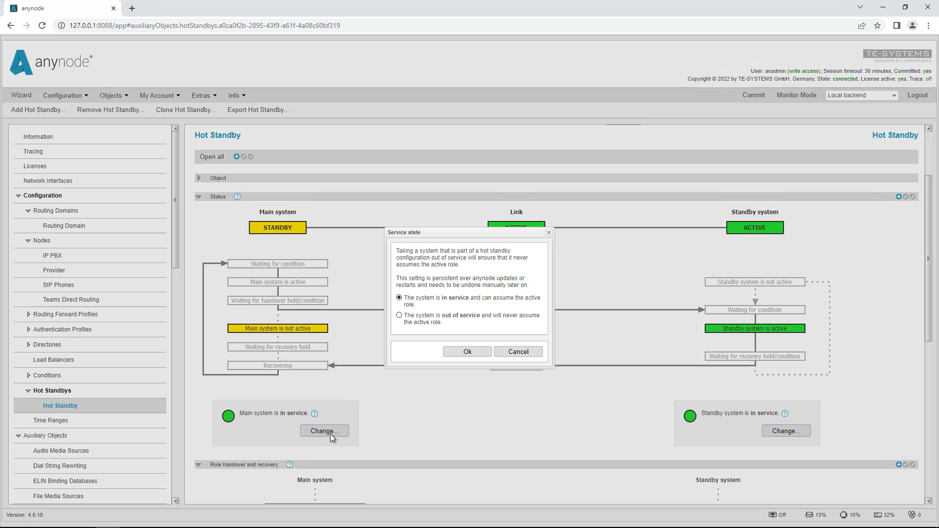
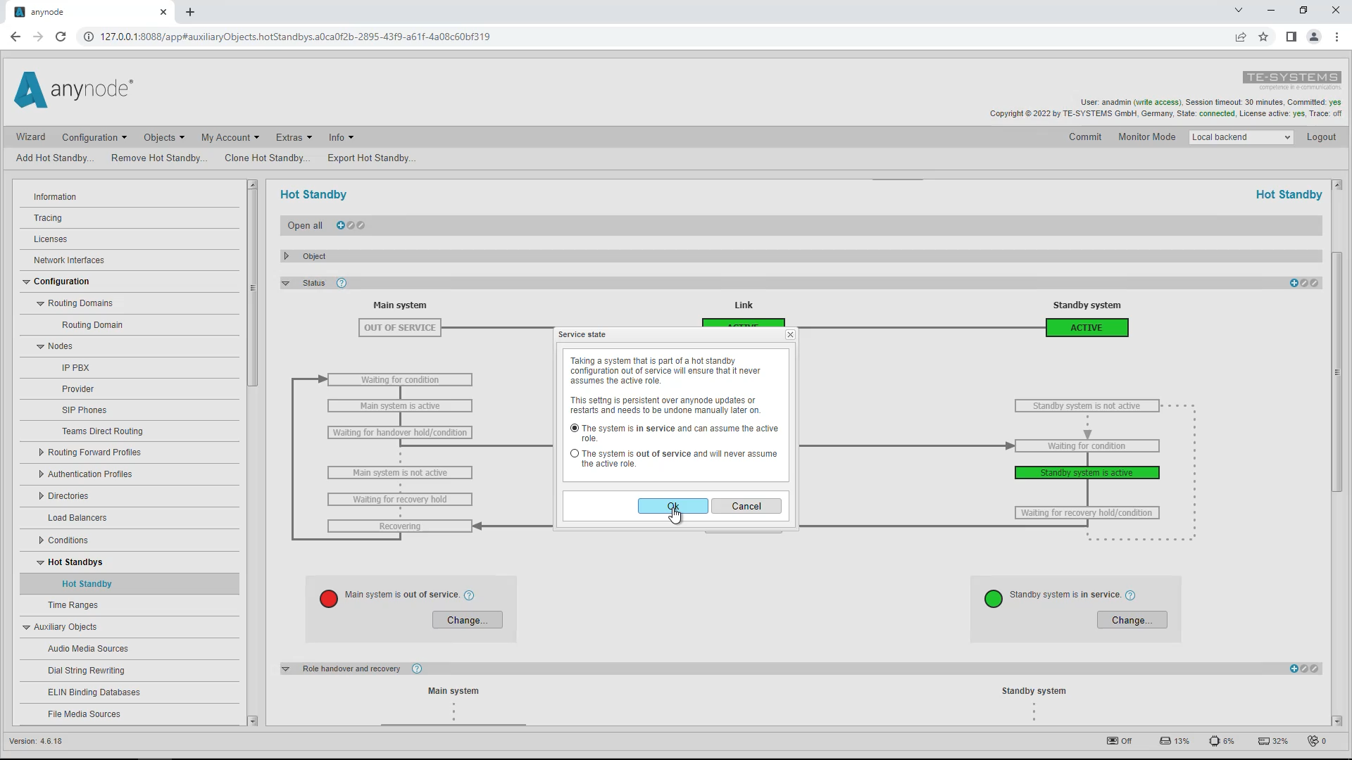
The Change button can be used to put a system into the “out of service” state. When this state is active, the “hot standby active” condition is permanently set to false and the “not active” condition is permanently set to true, as this system will never assume the hot standby active state for this period. If these conditions are not used, then the out-of-service switching will not affect the running operation.
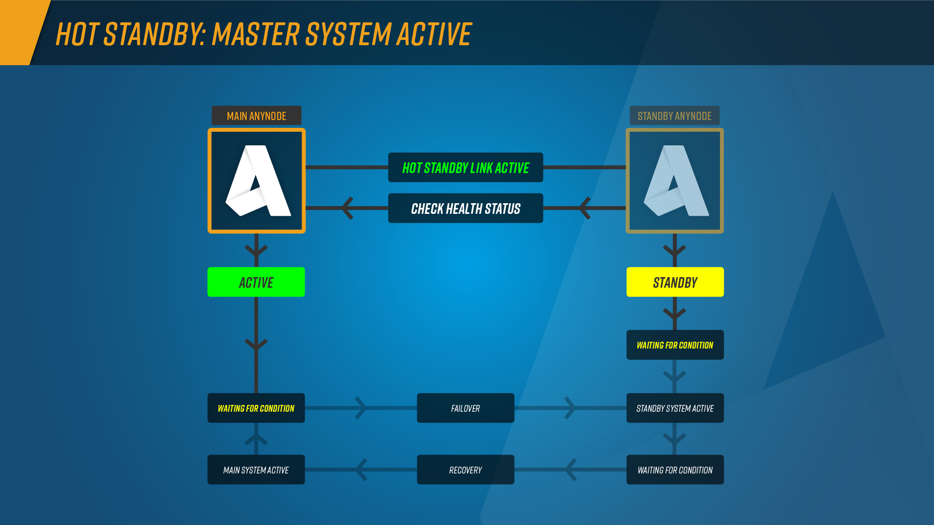
If the primary anynode instance is still active and not in maintenance mode, anynode will ask if the primary system should be taken out of service. If not, the primary system will immediately resume the active role. In our example, we want to perform a manual recovery.
Now the secondary standby system has taken over the active role.
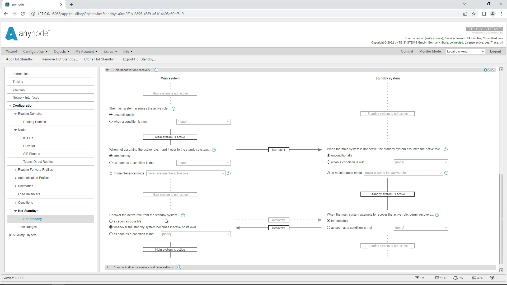
When the primary instance is available again, it depends on the settings whether the recovery to the primary system is immediate or whether a manual recovery is required. We will take a closer look at the settings for this in a moment.
It can be advantageous in practice to use manual recovery to minimize disruption. This way, recovery can be done outside business hours.
Click Recover to switch back from the standby system to the primary instance.
Settings Role Handover and Recovery
These settings control the behavior in the event of failover and a recovery:
The flowchart shows what happens when the primary anynode instance becomes unavailable, when the standby server should take over, and how and when recovery back to the primary anynode should occur.
Calltest
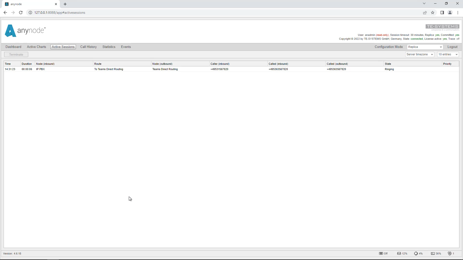
We now perform a call test. For this, we have put the primary system out of operation. The secondary anynode takes over all tasks at the moment. In Monitor Mode in Active Sessions, we can observe that the call is routed correctly and reaches its destination. At the same time, the primary system can be maintained.
Remove Replication and Hot Standby
If you want to undo the hot standby and replication, be sure to follow the order. It is best to proceed in the reverse order of the setup. First, reset the set Operational State Condition everywhere.
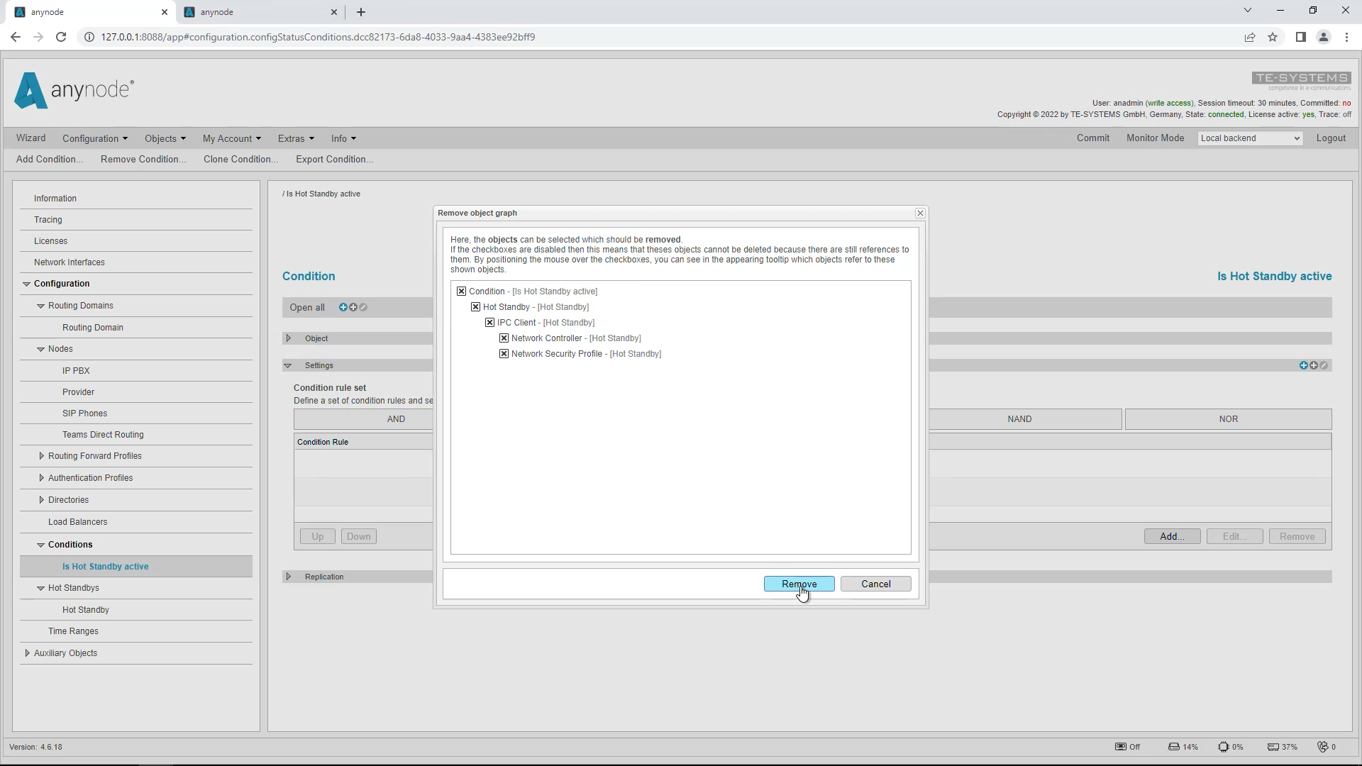
Go to “Conditions” in the left menu tree and remove the conditions with “Remove”. Be sure to remove the Hot Standby object as well.
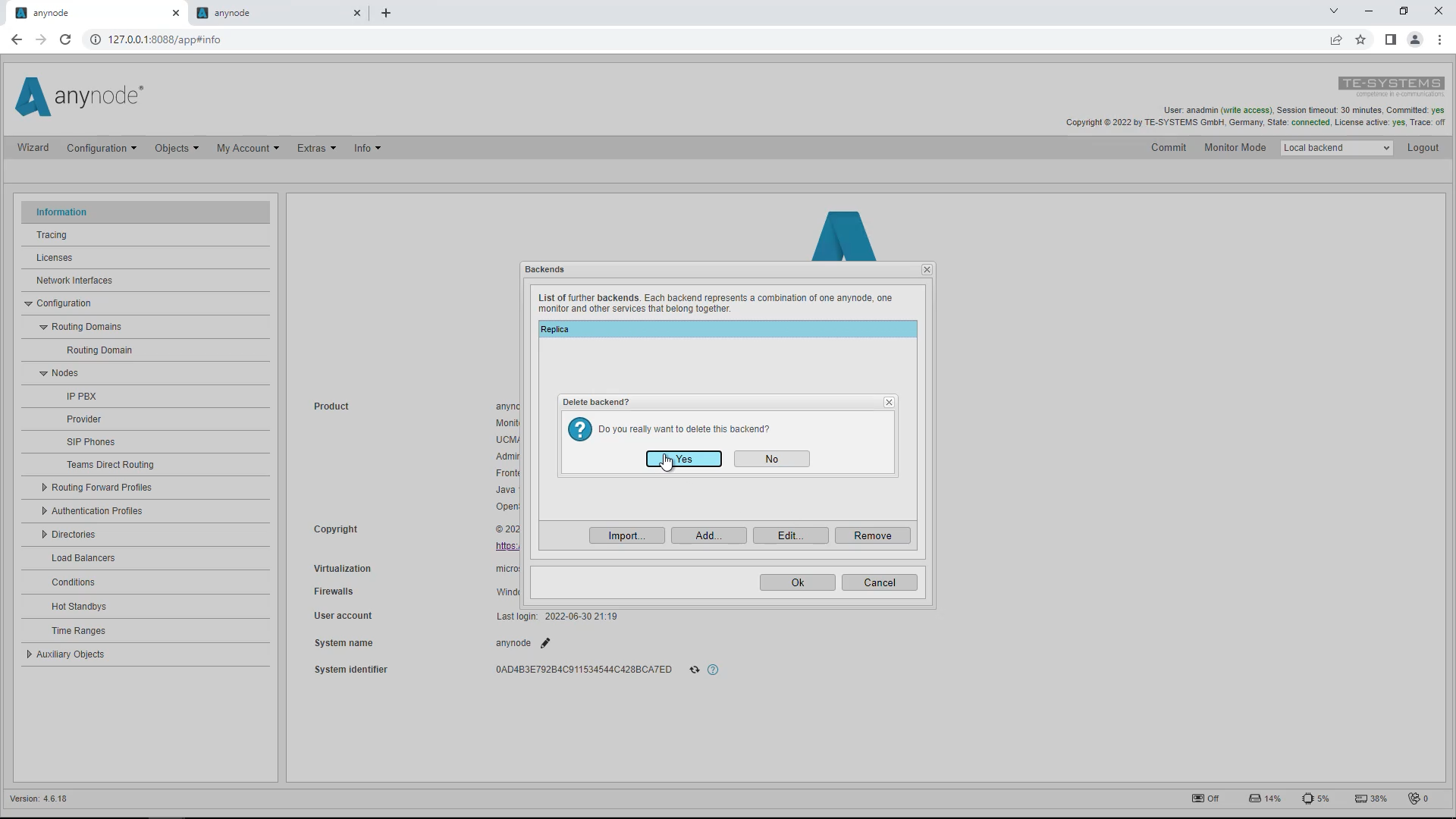
If you want to change the secondary system back to a primary standalone system, you should start on the primary system first and find and remove your secondary system from the list of remote backends.
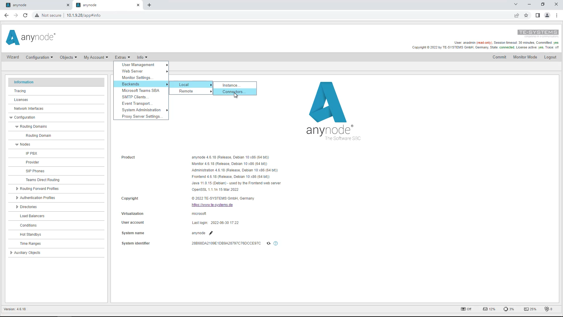
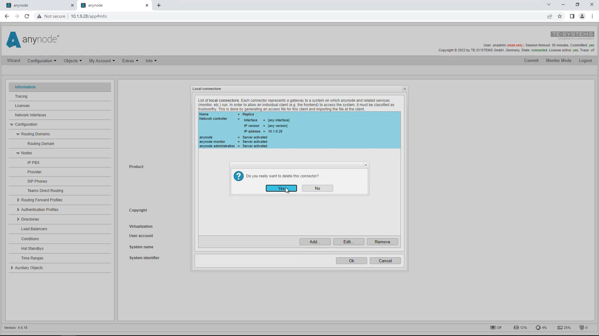
You will not be able to switch to the secondary system now. Log into the secondary system and start the anynode frontend there. Under “Extras”, “Backends”, “Local” and “Connectors” you will find the local connector.
Select it and remove it with “Remove”. Confirm the question if you really want to remove it with “Yes”.
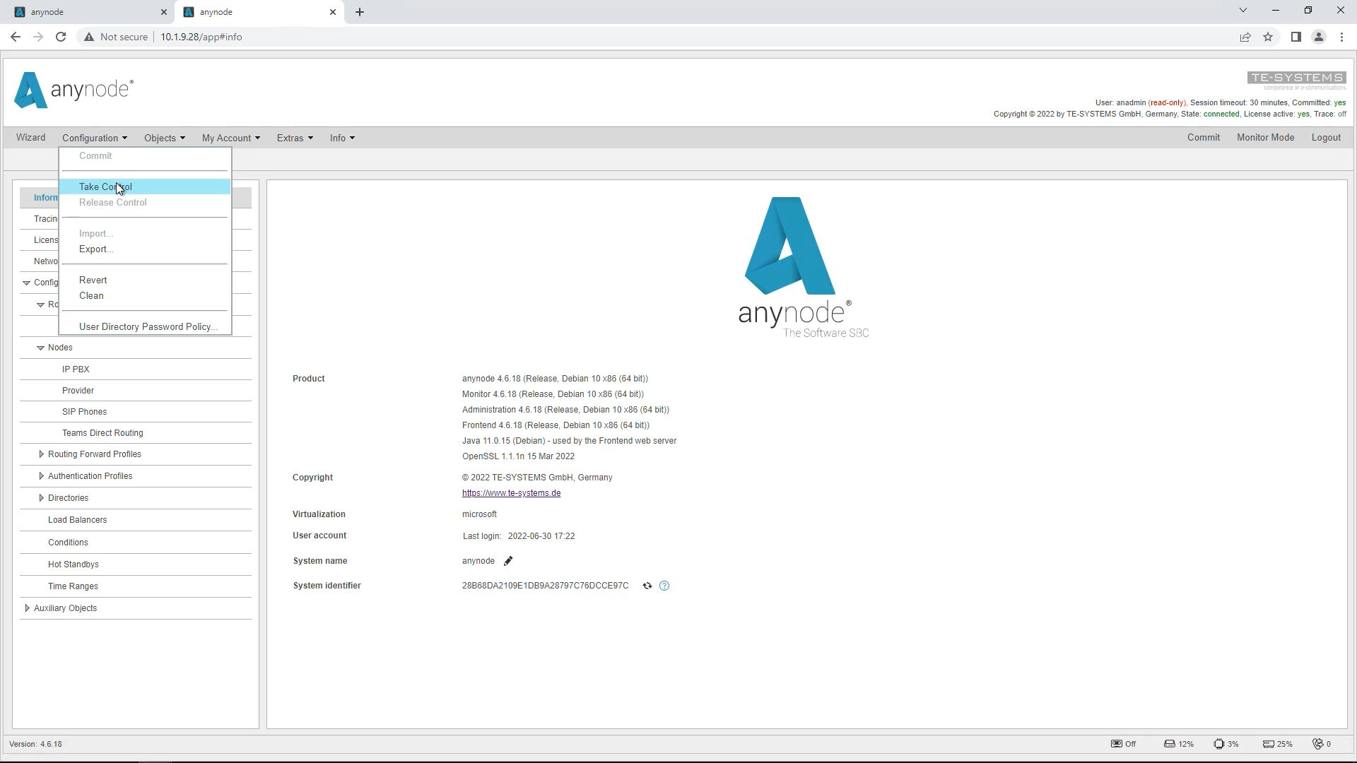
With this, the secondary system becomes an independent primary system again. Then take over the write permissions with “Take Control”.
We have now reached the end of this video tutorial and thank you for your attention.


